question

mr-susan avatar image
mr-susan asked

Any pointers? A mock up wiring diagram for my new Multiplus 12/500/20

Hi all,

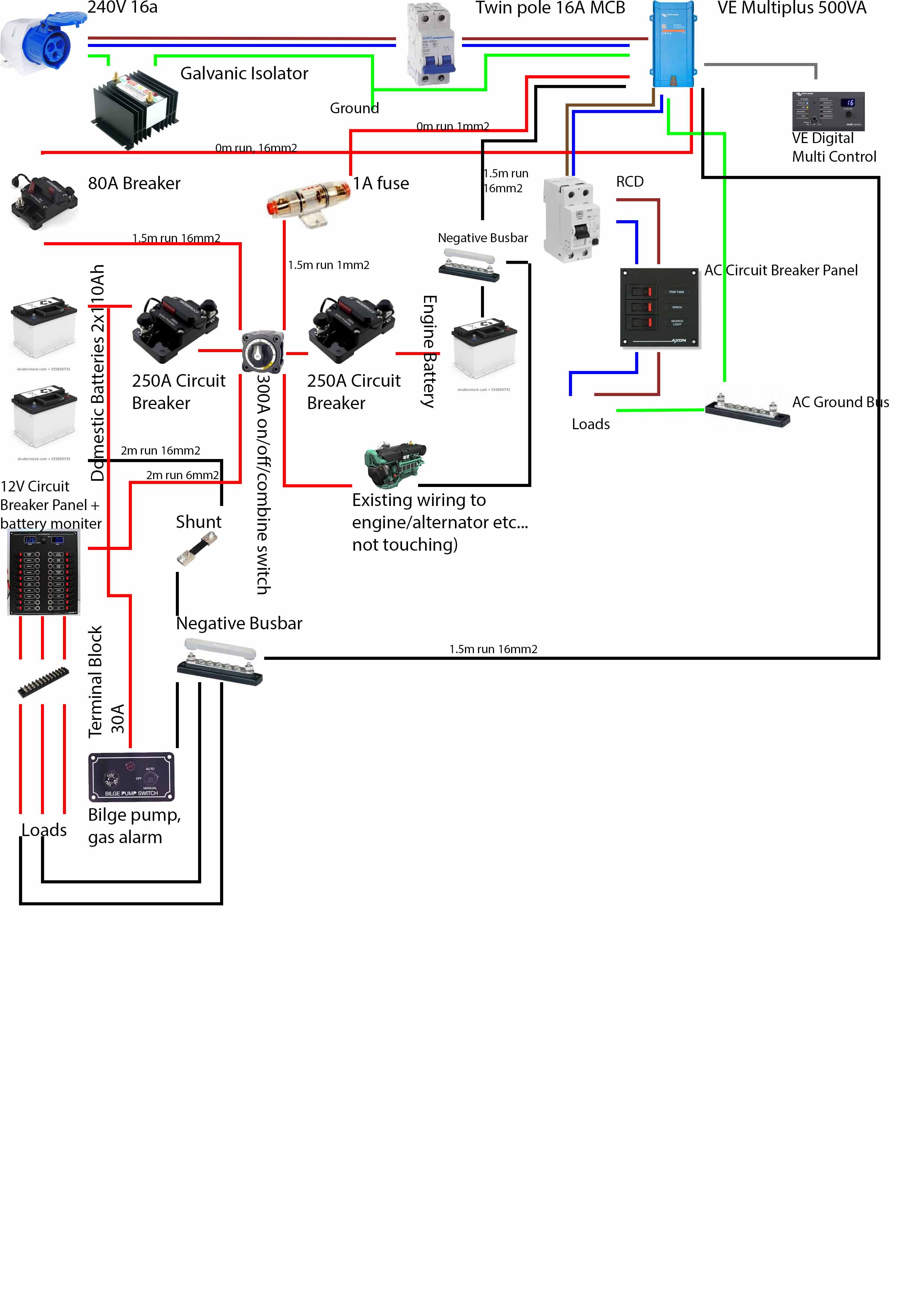
I have found some previous threads from here very useful and knocked up a wiring diagram last night to fit my new Multiplus 12/500/20 which I was hoping someone of superiour knowledge might be kind enough to scan over.

Most of the kit in this diagram is already aboard but I want to move a few bits around (e.g. RCD is in an ugly place and want to add the AC circuit breaker panel next to the DC one).

I am not an electrician but have had to undertake many repairs on electrical equipment at sea or in remote places on a variety of vessels (never my own) so hopefully I am not too far off the mark. But please show me where the gaps in my knowledge are and where I need to read up.


Cheers,

MultiPlus Quattro Inverter Chargerwiring diagramyacht
diagram.jpg (394.3 KiB)
1 comment
2 |3000

Up to 8 attachments (including images) can be used with a maximum of 190.8 MiB each and 286.6 MiB total.

Rob Fijn avatar image Rob Fijn commented ยท

hello Sir, there is no diagram attached.


0 Likes 0 ยท
3 Answers
ur12vman avatar image
ur12vman answered ยท

@Mr Susan Greetings, Nice diagram, what software did you use to make that?

Is the 1Amp fuse in the top left of the diagram being used for voltage sense? If so, then it should be connected directly to its source battery terminal to best determine the voltage drops across the circuit breaker and main battery switch and all its connections. Of course if the distance between the battery and inverter are very short, that voltage sense may not be needed at all. Test with a meter to find the voltage drop with the charger doing its best output. I assume that you are not really using that exact fuse pictured for a 1 amp circuit? An ATC in a covered holder is more appropriate. : )

You need a fuse or CB within 18" of the battery for your bilge and gas alarm power, the built in fuse protects the pump and wiring downstream of the fuse, whereas the fuse at the battery protects the boat from a short in that wire between the battery and the fuse in the panel.

The 80amp breaker that looks like its feeding the Multi from the house batteries is oversized. The max draw of your inverter should be 41 amp, so a 50 or 60 at most is a better choice.

Do you have a trickle charger on your starting battery? Does the Multi have a starting battery charger output?

I would not have circuit breakers on the combine circuit, perhaps that is a EU standard, I see that your diagram is in metric, so assume you are in the EU. The US standard does not require a CB for a combiner. If it works, it's not hurting anything, but the day you need to combine batteries to get the boat started is the day those breakers will pop repeatedly because of the inrush current to the dead starting battery combined with the current from cranking the starter could cause you grief if you are wanting to get away from the rocks in a hurry. Of course if you are cranking a tiny sailboat engine or outboard, that may not be an issue. Test your starting current and figure your max inrush to a dead battery and discover if 250amp is enough.

Of course I would not endorse anything here without actually seeing your build quality, tools used (proper crimpers especially), proper connectors, proper wire size, support of the wiring and all the other standards required in building a quality electrical system. The diagram is the easy part. Good luck, Ron

2 |3000

Up to 8 attachments (including images) can be used with a maximum of 190.8 MiB each and 286.6 MiB total.

mr-susan avatar image
mr-susan answered ยท

Hi @Ur12VMan/Ron,

Thanks so much for taking the time to look through and raise some queries/point out some bits I missed. I know its not yet complete. I used photoshop. What software would you recommend? It was a bit slow on photoshop.

The 1amp fuse is for the trickle charge from the multi to the starter battery. I should also add a temp sensor in there from the multi. Yes the pictures are just random grabs from google so exact fuses etc... arent shown. Point taken on the ATC though.

The fuse for the bilge pumps etc... was an oversight. Ill add that in right next to the battery.

I too thought the 80amp breaker was overkill but got the number from the datasheet: https://www.victronenergy.com/upload/documents/Datasheet-MultiPlus-500VA-1600VA-EN.pdf It says the peak power is 900w which led me to arrive at the 80amp breaker.

I see what you mean about the circuit breakers on the combine circuit. It is just a small sail boat engine (55hp) but I will check what the engine actually draws before finalising and ordering any parts. The combine switch is only rated to 300amps so I put those in to protect the combine switch (I have come across a melted battery isolator switch on another vessel which just sticks in my mind). Might be better to ditch the 250 amp breakers though... will have to think some more.

Thanks again. I will keep working on it.

2 |3000

Up to 8 attachments (including images) can be used with a maximum of 190.8 MiB each and 286.6 MiB total.

kai avatar image
kai answered ยท

Typically on the DC side fuses are used, as DC breakers can be expensive. DC breakers are rated for breaking DC (up to their defined limit); AC breakers are either not rated for DC or need severe downrating when used in a DC environment.

1 comment
2 |3000

Up to 8 attachments (including images) can be used with a maximum of 190.8 MiB each and 286.6 MiB total.

mr-susan avatar image mr-susan commented ยท

I understand that usually fuses are used in DC circuits but if you consider sailing somewhere remote where you cant just pop out and pick up some new fuses then using circuit breakers wherever you can makes a lot of sense.

Of course you can carry a lot of spares in the first place but that doesnt seem like an advantage over circuit breakers.

Having said all that. Looking at getting the main DC switch panel made, it does look like I will be using normal switches with a fuse box behind.

0 Likes 0 ยท