question

dc-generators avatar image
dc-generators asked

SmartSolar 150/85 showing input voltage when nothing connected.

I have an issue with SmartSolar 150/85 showing pv voltage equal(-0.5v difference) to battery bank voltage even when no pv input is connected.

As this is a new unit purchased for testing purposes, does anyone have an idea what might be causing this?

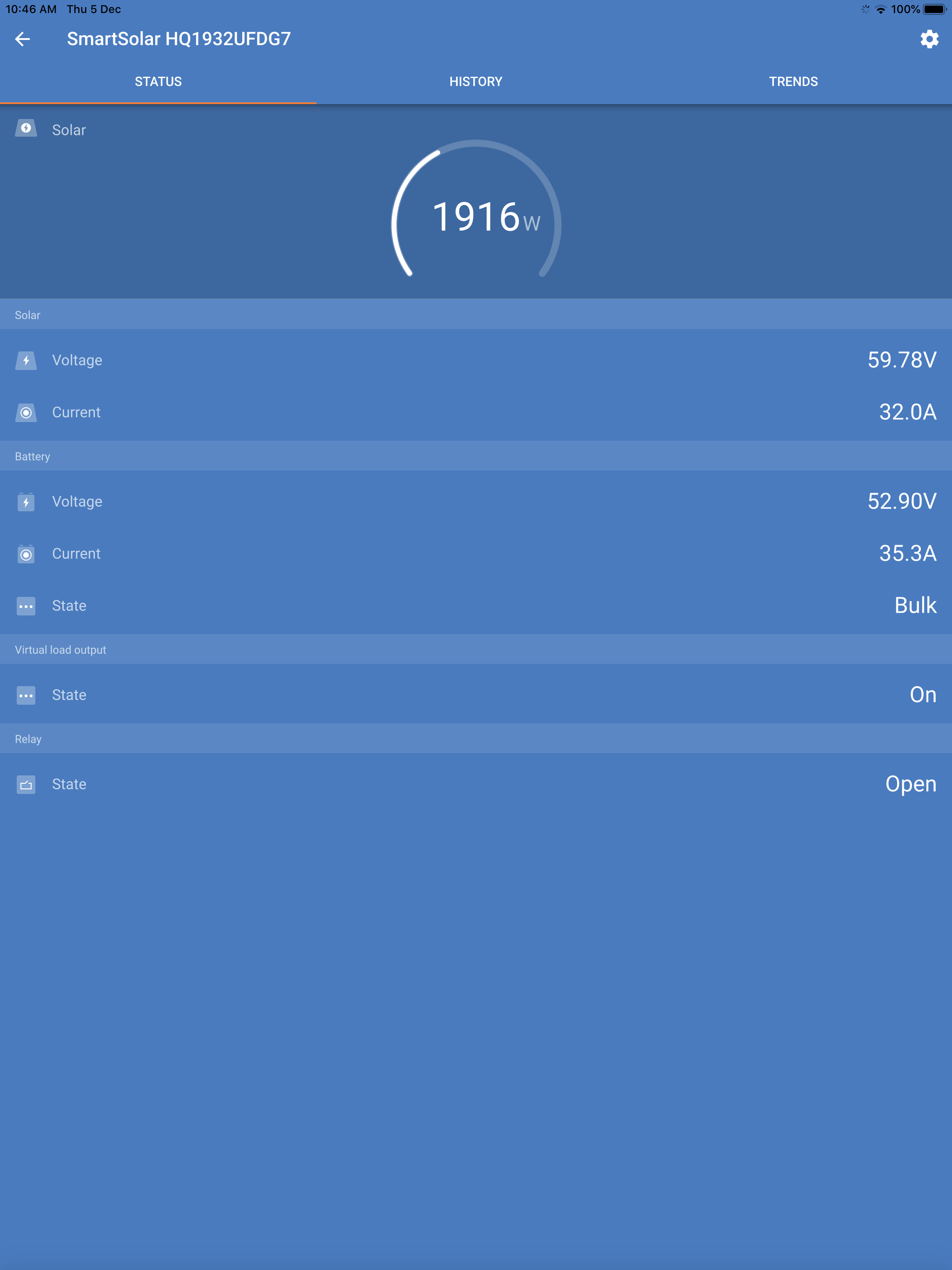
The unit can still charge correctly, but after removing input source, the pv voltage shows a higher voltage than battery bank until Remote jumper is removed. Needs to be reset otherwise it stays in Bulk mode even though no pv is connected.

It obviously has been damaged during testing, just not sure what to check for repairing.

Also finding it difficult to remove blue cover :)

Any help would be greatly appreciated.

MPPT Controllersdc system
2 |3000

Up to 8 attachments (including images) can be used with a maximum of 190.8 MiB each and 286.6 MiB total.

3 Answers
Guy Stewart (Victron Community Manager) avatar image
Guy Stewart (Victron Community Manager) answered ·

Hello @DC Generators

Was reverse polarity connected to the battery terminals? That can cause an issue like this. Though that is usually the end of the charger, and it does not work anymore (or only 1A).

But you say it still works? Just does not read PV voltage correctly?

There is nothing you can repair inside, do not attempt to open it up. Then you will surely destroy it.

The next step is to fill out this form.

5 comments
2 |3000

Up to 8 attachments (including images) can be used with a maximum of 190.8 MiB each and 286.6 MiB total.

dc-generators avatar image dc-generators commented ·

Hello @Guy Stewart.

No reverse polarity at all.

Used a DC generator as replacement to pv input.

On first day of testing I used 2 x dc contactors from battery bank to generator as the pma uses the bank to start the engine, then charges the bank after ignition through the mppt. The contactors only activate during startup then disengage when engine is running.

At one attempt, I forgot to disengage the contactors, so engine was running and output was going through pv input of SmartSolar and to the battery bank directly.

I think thats when it was damaged.

The issue now is that current can flow from battery side to pv side. Makes sense?

Although the unit is still working(strangely enough) and producing 30-40amps @ 48v during bulk. Only ran for 10mins up until now.

So nothing is servicable inside?

What happens in such a situation?

0 Likes 0 ·
Guy Stewart (Victron Community Manager) avatar image Guy Stewart (Victron Community Manager) ♦♦ dc-generators commented ·

Ok, it is an unusual situation for a solar controller, not one that it is designed for.

Perhaps some diodes outside might help prevent this back flow issue?

Really, there is nothing serviceable inside.

What happens next is you fill out this form. The next steps aren’t something we can solve here on the community.

0 Likes 0 ·
dc-generators avatar image dc-generators Guy Stewart (Victron Community Manager) ♦♦ commented ·

Hello Guy.

Filled out the form and spoke to the distributor here in Cyprus. They forwarded the message to Victron but doesnt look like we will get any answer or assistance as it was used in a non conventional way.


Shame we couldnt exchange any details with Victrons technicians so we dont damage any other controllers in our following tests with a new units.


0 Likes 0 ·
jex avatar image jex dc-generators commented ·

With some of the Victron MPPT's the caps are potted to the case which makes removing the case an absolute pain in the ass.

Also, to say there is nothing serviceable inside is such nonsense. It's a electrical device made out of electrical components which if they fail can be replaced. It's not some magic blue box that does things. Are we supposed to bin the unit when the warranty runs out?

0 Likes 0 ·
Justin Cook avatar image Justin Cook ♦♦ jex commented ·

Nothing user-serviceable. Every single electronic component in existence says that there's nothing user-serviceable inside, and most of them are correct. I'm sure that, once the warranty is up, you can do what you like, at your own risk, to your components.

0 Likes 0 ·
tkmbe avatar image
tkmbe answered ·

Hello


Ups. That's the same I want to do in the future.

I tought this MPPT chargers are very nice instead of a battery charger. You have bluetooth connection and can read battery state etc.

Because there is no need to put a solar panel in my case on some places, I thought to put a DC supply with say 36V and feed to PV input, battery bank and on load output my wireless communication equipment. So you have charger, control unit and battery drain protection in one for the same price as a good battery charger.


Can you five me any hints what you did, that damaged PV input?

Anybody using such a configuration???

1 comment
2 |3000

Up to 8 attachments (including images) can be used with a maximum of 190.8 MiB each and 286.6 MiB total.

dc-generators avatar image dc-generators commented ·

Hello @tkmbe and @Guy Stewart (Victron Community Manager)

To give a you a better understanding of what I believe damaged the controller.

The dc generator uses the battery bank to crank the engine during start up. The generators dc output is connected to pv input.

During a test startup, the flow of current went from battery side of mppt to the pv input side. So battery bank was physically connected to pv input and to battery output side of mppt simultaneously.
As I don’t know how the mppt internals operate, I used normally open contractors to connect battery bank to generators output(also connected to pv input) to provide power during the startup phase. The generators controller was programmed to only operate the contractors during startup and disengage when engine was running, to go through mppt as a charge controller. If I had used normally open and normally closed contractors to never have battery connected directly to pv side, I believe the damage might have been avoided.


Reverse polarity never happened, that would have permanently damaged the mppt.

The only thing that has happened to mppt now from this test is that, after the generator shuts down and no current is being produced, pv input shows 60-90v (fluctuates randomly) and obviously 0 amps. Still thinks it’s in bulk mode charge. I therefore need to remove the remote pin to reset the mppt. After resetting, pv shows 0.5v lower than the battery bank side and State resets to Off.

Here is a screenshot during a test charge.

0 Likes 0 ·
shingsam avatar image
shingsam answered ·

Hi, this same issue with me. I think app have bug, but when i check input pv with volt meter they have 60V. Anyone have solution for it ?

I'm afraid it will demage pv.

2 |3000

Up to 8 attachments (including images) can be used with a maximum of 190.8 MiB each and 286.6 MiB total.

Related Resources

MPPT Product Page

MPPT Error codes

MPPT 150/60 up to 250/70 Manual

Additional resources still need to be added for this topic