question

Leslieanne avatar image
Leslieanne asked

Smartsolar 100/20 showing incorrect low battery voltage over VE smart network

Hi there,

This is a problem observed consistently since the major mppt upgrade from 1.39 to 1.4x.

Mppt smartsolar 100/20 networked with BMV700 (dongle located almost next to the mppt, with a 1.5m extension cable). When significant current is being supplied by the mppt, Victron Connect mostly displays its battery voltage about 0.2 V lower than the BMV, despite it receiving the data from the BMV via the VE smart network . The actual voltage at battery terminals, measured with multimeter, is exactly that reported by the BMV (both on the device itself and via the Victron connect app). The measured voltage at the mppt output terminals is higher, of course, due to voltage drop across the connecting cables (about 1.5m of 13mm2 cable). If I remove the mppt from the network it correctly displays this higher voltage. Rejoining the network returns it to the anomalous readings above.

This is not just a reporting glitch of the app. The mppt apparently โ€œbelievesโ€ these anomalous readings. As a result, the mppt switches to absorb at a true battery voltage about 0.2 volts ABOVE the setpoint. If only looking at the mppt values using Victron Connect you would never realise this - the apparent battery voltage, as shown in the app, stays rock-steady at the set absorb voltage. Meanwhile, as the current reduces during the absorb stage, the true battery voltage gradually comes back down towards the correct set value by the time it switches to float. (This is almost the opposite of the behaviour before the update, when the mppt would switch to absorb about 0.2 V too low and gradually come up to the set voltage...I'm not sure which is worse.....)

The photo below shows a period of about 7 minutes during bulk charging. The mppt is producing about 18 amps, except for a brief drop at about 4 minutes as a wisp of cloud passed. Initially the caravan fridge is drawing about 3 amps, then cycles off for the next 5 minutes. The BMV showing the correct voltage values is on left, and the inaccurate mppt values are shown on right, displayed simultaneously on two mobile devices. The spike in reported voltage on mppt about a minute after the start of recording, corresponds to the fridge cycling off. That may have briefly disturbed the bluetooth connection, causing the mppt to suddenly โ€œsee" its real output terminal voltage (higher of course than the battery voltage) but then over the next few minutes it slowly returned to โ€œseeingโ€ a voltage well below the true battery voltage.

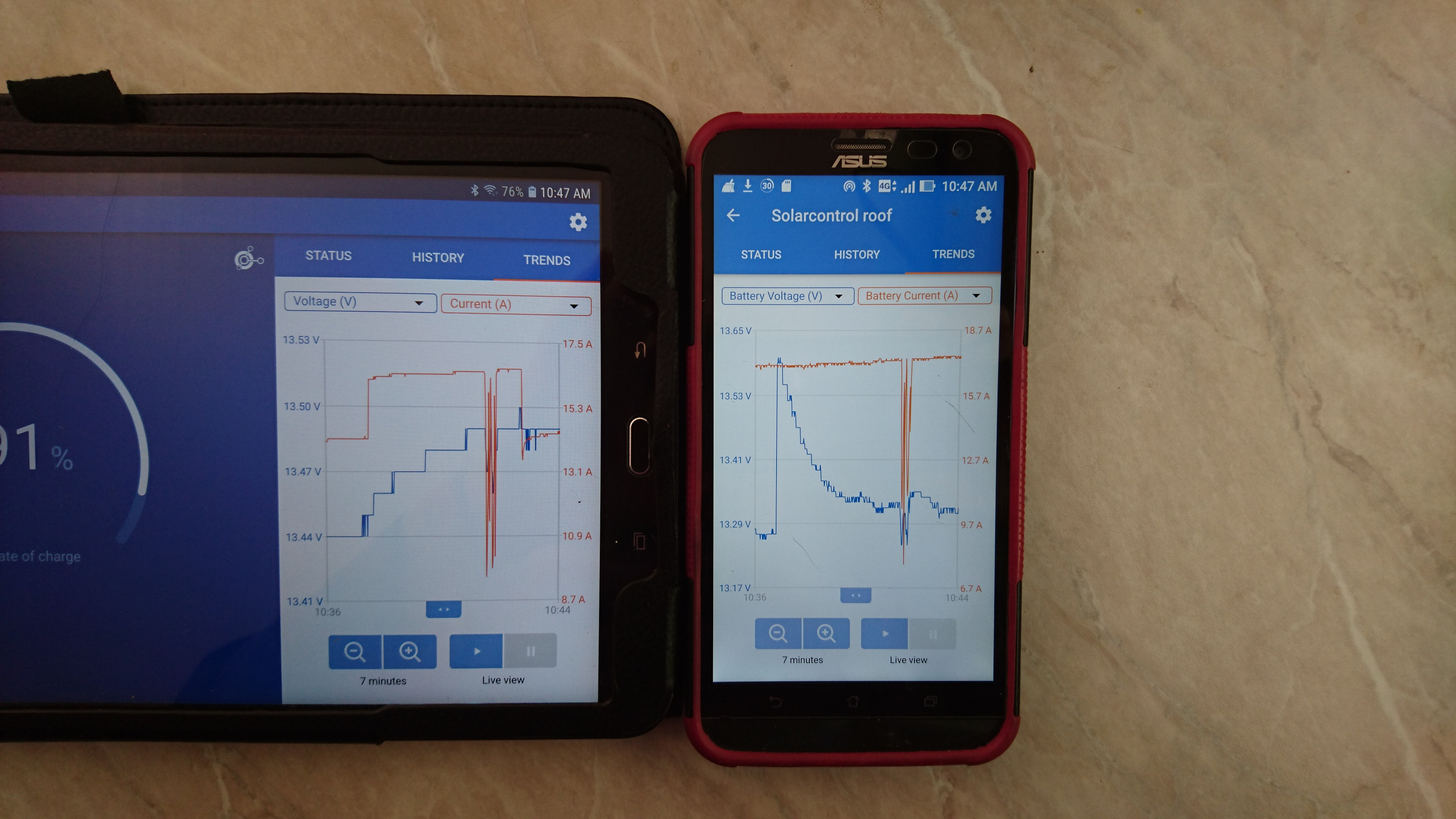
Possibly a glitch in the updated software? A bit annoying as could lead to overcharging of lithium battery.

Cheers, Leslie

@mvader

MPPT ControllersVE.Smart Network
2 |3000

Up to 8 attachments (including images) can be used with a maximum of 190.8 MiB each and 286.6 MiB total.

1 Answer
JohnC avatar image
JohnC answered ยท

Hi Leslie. I can't help with your particular issue. But if you suspect a firmware problem, then bring all your kit up to scratch there. I just checked my own system and updated to 1.46 on the mppt. (I use VRM, not BT)

There was indeed an issue in the stepup from 1.39, and it was withdrawn for some reason and reversion recommended. Can't remember why, and it's not important.

Bring yourself up to scratch and try again..

3 comments
2 |3000

Up to 8 attachments (including images) can be used with a maximum of 190.8 MiB each and 286.6 MiB total.

Leslieanne avatar image Leslieanne commented ยท

Hi John,

Thanks for the reply. Sorry I was not clear. Everything is indeed fully up to date, and the problem has been present at least through the last two updates. It may well have been present since the very first update from 1.39, but I woulc not have noticed. As I explained, you will only see this easily if you observe the mppt and the bmv at the same time. Even if you switch quickly beteeen the two on one mobile device, it is confusing, especially so if the insolation is varying, since the mppt takes some minutes to stabilise its reported battery voltage from the ve smart network. I am certainly still confused how things work. But I have observed it enough over the last month or two, that I know that at significant amps it repeatedly does not switch to absorb until the real battery voltage is well above the set point.

0 Likes 0 ยท
JohnC avatar image JohnC โ™ฆ Leslieanne commented ยท

Ta for the clarification. Agree it's strange.

Consider that temp compensation will affect the mppt's target V's. On it's own it will lock-it-in for the day, and of course vary from the setpoints depending on how hot it is, but if you're using the BMV temp sensor it will follow that and adjust in real time.

Might that be related?, and that 'tapering' V on the phone pic a result of the sensor detecting more temp? Even something stupid like sun on the sensor?

But I can't even make your graphs fit with that scenario.. Anyone else?

0 Likes 0 ยท
Leslieanne avatar image Leslieanne JohnC โ™ฆ commented ยท

Lithium bats. Temp compensation disabled.

The "tapering" seems to be part of the software algorithm. Have a look at the picture below. In this case the mppt is in the " off " state ( no current from it) so that it settles at the true battery voltage. The battery is being charged at 25 amp from a bluesmart charger which is sharing the same 1.5m feed to the battery, so that the voltage at the mppt battery terminals is well above the steady true battery voltage of 13.68. With no amps thru the mppt it first demonstrates the actual output terminal voltage, then slowly settles to the actual battery voltage as sent by the bmv. Takes a few mins each and every time that one opens victron connect to look!!!!!

0 Likes 0 ยท

Related Resources

MPPT Product Page

MPPT Error codes

MPPT 150/60 up to 250/70 Manual


Additional resources still need to be added for this topic

VE.Smart Networking Manual