question

alexbrink avatar image
alexbrink asked

How to calculate custom tank "Sensor Level" percentage.

OBJECTIVE:

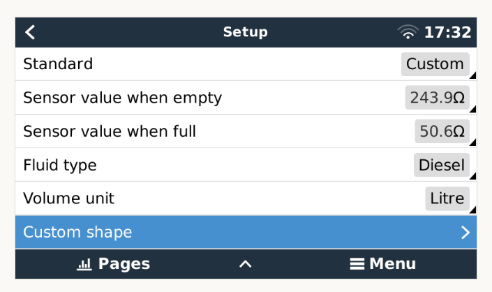
Set the custom parameters for an irregular shaped tank with a 600mm 30-240ohm KUS tank sender.

Cerbo GX.

QUESTION:

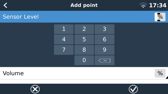
How does a user calculate with mathematical certainty the "Sensor Level" in % to calibrate a known volume in %?

EXAMPLE:

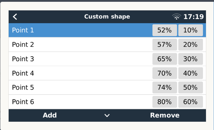
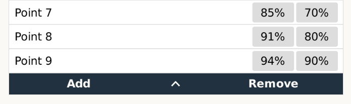
The photo attached show the set points that have been added for my particular installation to work correctly.

Take Note the sensor value at Point 1 is 52% and the volume is at 10% which corresponds to approximately 120mm of rise in the float at 100 Litres.

(I have calibrated all these values to work correctly by trial and error)

cerbo-tank-cal.png

1721201628390.png

1721201671045.png


1721201544905.png


tank monitor
cerbo-tank-cal.png (43.1 KiB)
1721201544905.png (42.5 KiB)
1721201628390.png (19.5 KiB)
1721201671045.png (28.3 KiB)
5 comments
2 |3000

Up to 8 attachments (including images) can be used with a maximum of 190.8 MiB each and 286.6 MiB total.

Alexandra avatar image Alexandra ♦ commented ·

Since it is an irregular shape a linear answer is not possible as you know.

You would have to fill the tank with known quantities step by step. Take a reading at each step. And make that work on your scale.

So if your tank is 100litres and you want 10% increment steps. Fill with 10l take the reading. Add 10l take a reading. Repeat.

Unless you really want to math the math.

0 Likes 0 ·
alexbrink avatar image alexbrink Alexandra ♦ commented ·

Lets say a user has these exact measurements for each increment of 100 litres of their tank. ( In most cases the soundings from the ships stability book or a sight glass would give you the measurements from top of tank.)

Is there a correlation that would allow a user to math the math to convert a sounding measurement to correspond to a Sensor Level %? (i.e. The only unknown being the Sensors % for the given volume)


0 Likes 0 ·
nickdb avatar image nickdb ♦♦ alexbrink commented ·

You would need to do some geometry and volume calculations.

The goal is define multiple points that when the sensor reports X capacity that it knows the volume is actually Y at those points.

0 Likes 0 ·
alexbrink avatar image alexbrink nickdb ♦♦ commented ·

It is difficult to understand how the sender float be almost at the bottom of the shaft and require a Sensor Level value of 52 %.

I guess what I'm trying to convey is, What is this "sensor level" a percentage of ? (Victron?)

It would preferable that the software be changed to input the current OHM reading and the level of percentage you want your tank to read at.

40ohms = 10%

53.5ohms = 20%

etc

At least you can see what the float is reading at any given position.

The user can just fill the tank up with a measurable quantity to the Full mark then divide that by 10 and then remove 1/10th and record that current ohm reading and set the volume level at 90%, so on so forth.

or better still, The user sets ohms and a known quantity of fluid. The user needs just fill their tank with X amount of liquid and take a reading in ohms and call it X amount of litres in the software.

P1 = 43ohms at 100 litres

P2 = 54 ohms at 200 litres

etc


0 Likes 0 ·
nickdb avatar image nickdb ♦♦ alexbrink commented ·

Tanks have a volume, the % is a relative indication of that volume at a point in time.

This is a way of providing a reference point to a system that at a specific reading the actual level at specific points is different, so it can calculate an approximate non-linear value.

The GX tank 140 manual gives a reasonable example for a tank with a wider top.

0 Likes 0 ·
0 Answers