question

deandavis1 avatar image
deandavis1 asked

MPPT showing erroneous voltages with SmartBattery Sense

I have a SmartSolar MPPT 100/50 with SmartBattery Sense (SBS) running with 1.42 firmware. I've been suspicious that the MPPT would sometimes not use the SBS voltage as a result of seeing impossible battery max and min voltages.

Today I was able to prove this as the system is locked in this problem state. Attached are three VictronConnect (VC) screen shots as follows:

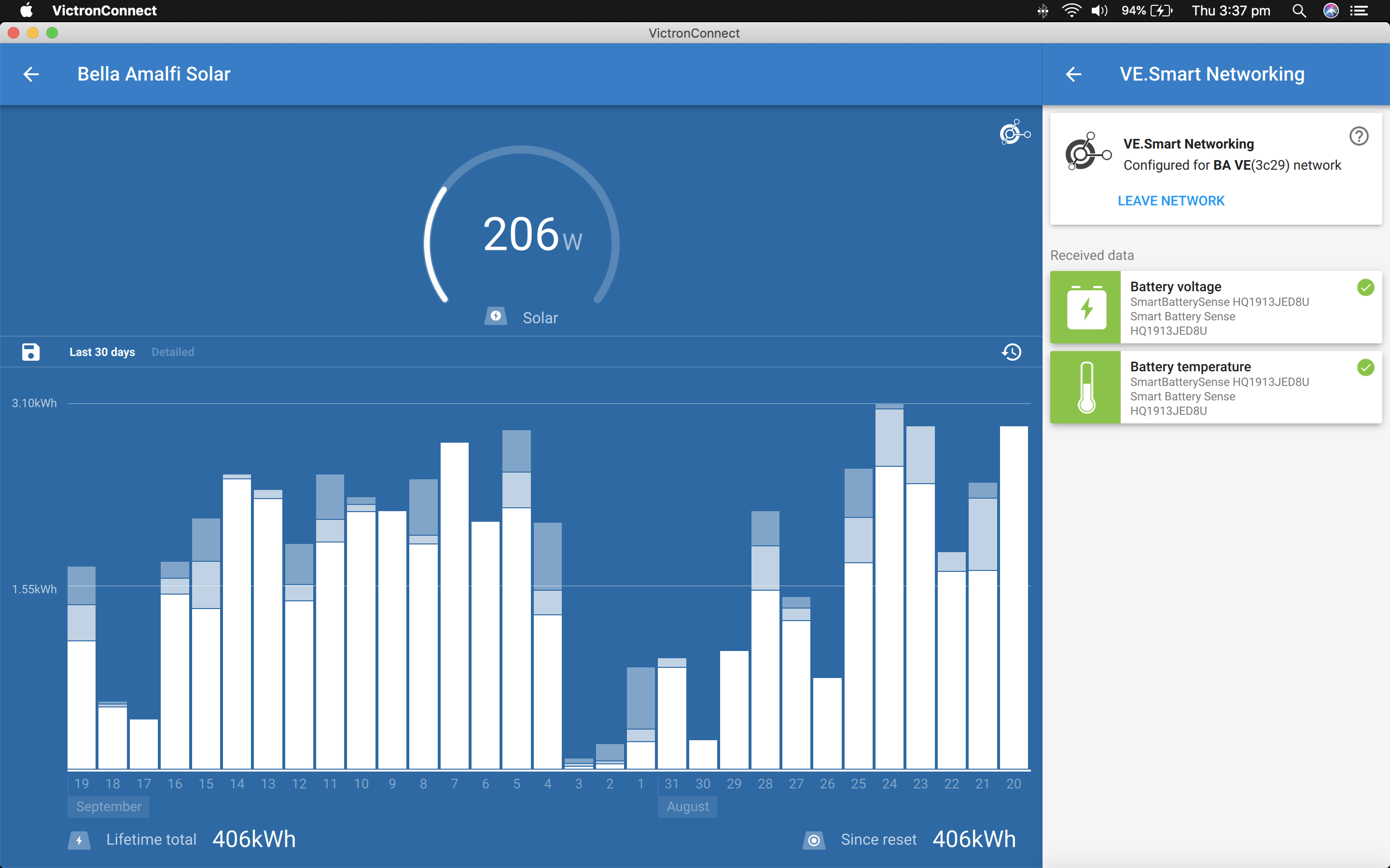
  1. MPPT VE Network confirming its connected to SBS and receiving voltage and temperature data.
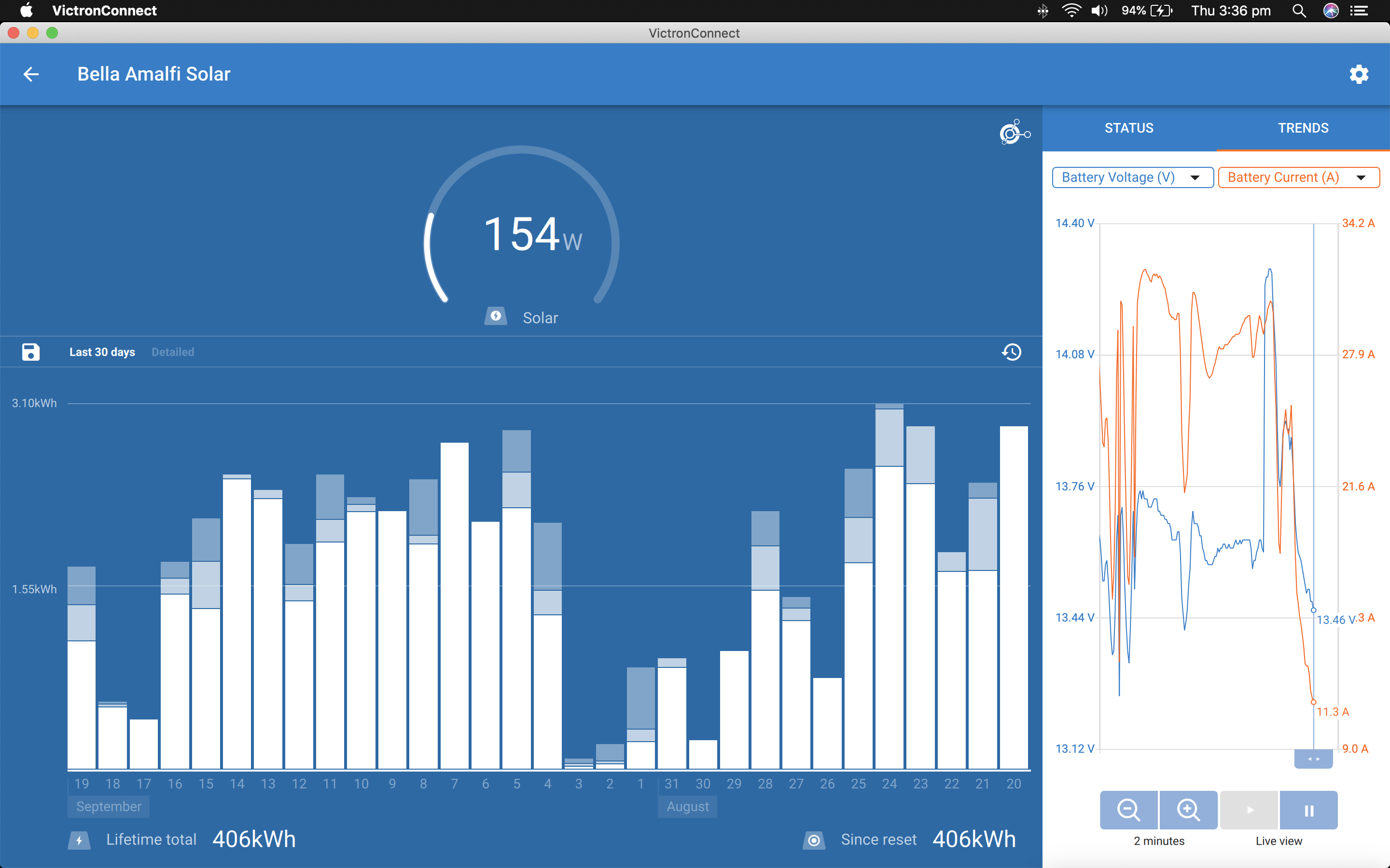
  2. MPPT battery voltage trend graph over 2 minutes.
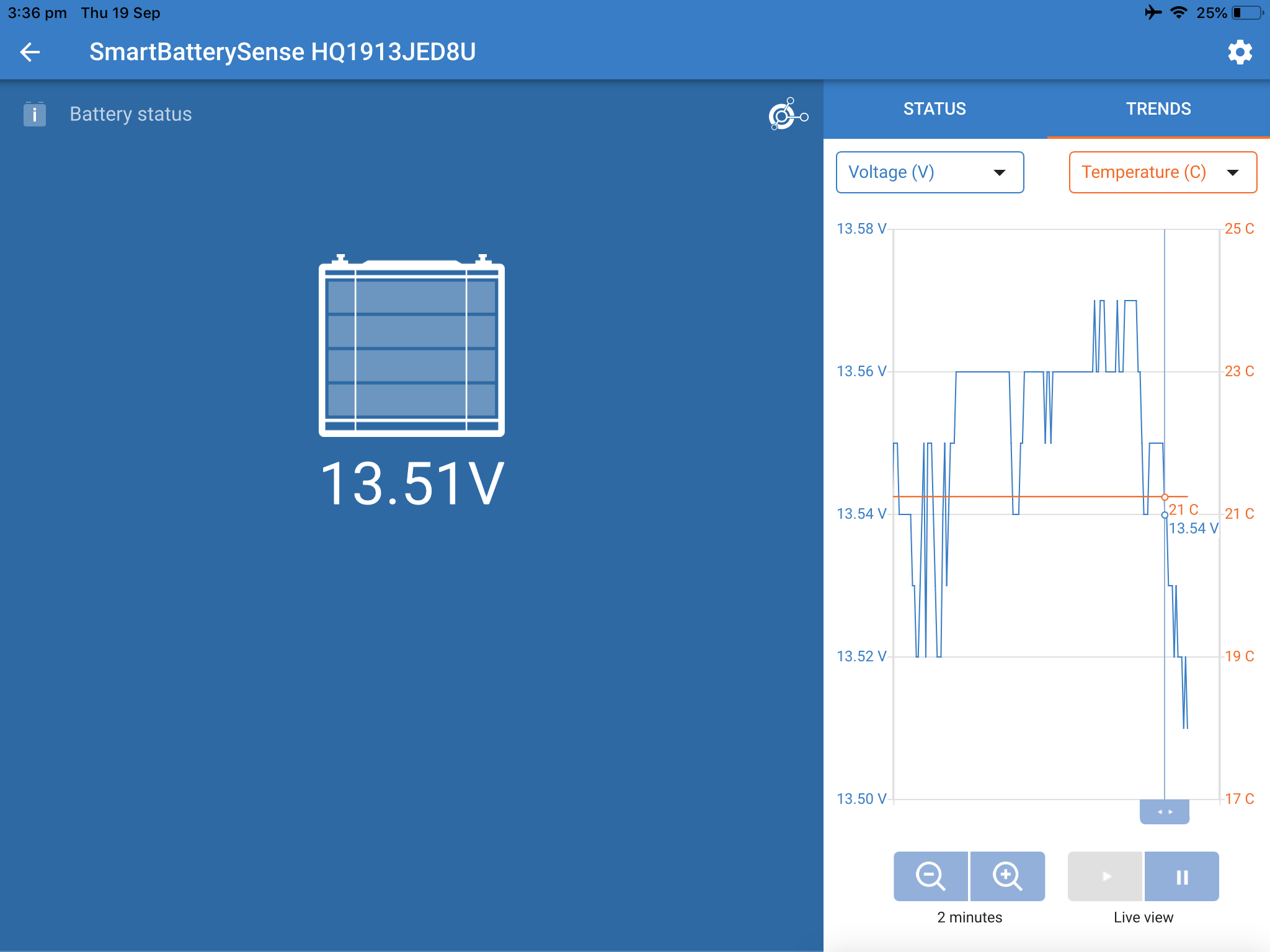
  3. SBS battery voltage trend graph over exactly the same time.

This has captured the moment when the MPPT is saying its using SBS voltage data but in fact is not.

The following notes as some background:

  • The SBS is mounted directly on the battery terminals and within 500mm of the MPPT.
  • The MPPT passes through various BMS components (eg Fuse, Switch, Shunts) and hence has some resistance (Thus the need for the SBS).
  • All connections are tight
  • I have performed a power cycle of the SBS
  • I have disconnected and reconnected the MPPT from the VE Network
  • I have software disabled and re-enabled the MPPT
  • I have NOT performed a power cycle of the MPPT but will try this tonight after the sun goes down
  • At this stage the system remains locked in this state.

I believe there should be no way this could happen as a result of installation and is potentially a major software bug.

MPPT ControllersSmart Battery Sense
venetwork.png (490.7 KiB)
mppt.png (592.4 KiB)
smartsense.png (192.1 KiB)
2 |3000

Up to 8 attachments (including images) can be used with a maximum of 190.8 MiB each and 286.6 MiB total.

5 Answers
Mark avatar image
Mark answered ยท

As far as I know, in order to ensure instantaneous response to rapid voltage variations (which may not arrive fast enough over a Bluetooth interface), the MPPT is still the primary source for voltage and the SBS is used to 'correct' the initial MPPT voltage measurement for cable losses/voltage differences and for temperature compensation.

So if you see a weird instantaneous/brief voltage variation only on the MPPT log, then I suspect that the issue is actually related to the MPPT or more likely the related wiring, connections or fusing. There may be an intermittent connection somewhere.

I would advise to carefully go over every termination and rectify/replace any connections that look suspect. Even replace the entire MPPT to battery wiring and fusing (temporarily eliminating as many extra compoments/terminations as possible) if you happen to have some some spare suitable wiring and another fuse holder + fuse available - then retest.

If the issue still exist's then it could be the actual MPPT.

Lastly, is it possible that the spike could be real? Did a large load happen to turn off at that time while the charge current was relatively high at ~30A?

I can see that the current drops down to ~10A after the voltage spike which indicates to me that either the load or solar conditions also significantly changed at the same time.

That could also cause a similar brief voltage spike if you have a proportionally small battery bank.

2 |3000

Up to 8 attachments (including images) can be used with a maximum of 190.8 MiB each and 286.6 MiB total.

deandavis1 avatar image
deandavis1 answered ยท

Thanks for your quick response. Wow I'm absolutely blown away if the Victron MPPT can not use an external sensor to measure battery voltages. Yes the resistance between the MPPT and battery is real due to the need for BMS with lithium batteries (or any battery). This is something I covered in a previous thread (https://community.victronenergy.com/questions/9795/bluesolar-terrible-voltage-accuracy.html?childToView=9868#answer-9868). Here I point out that the MPPT is measuring its output not the battery voltage.

These controllers are are designed to pass significant current. At these high values the voltage drop would be a major issue when 0.1v is so important for lithium charging. During testing today there was a lot of variation in solar and hence current and hence voltage drop so it was easy to spot.

Can anyone confirm the "MPPT is still the primary source for voltage and the SBS is used to 'correct' the initial MPPT voltage" and what is meant by "correct"?

If this is the case then the previous thread needs to be re-opened about Victron voltage measurement.

2 comments
2 |3000

Up to 8 attachments (including images) can be used with a maximum of 190.8 MiB each and 286.6 MiB total.

Mark avatar image Mark โ™ฆโ™ฆ commented ยท

I'm not understanding what your complaint is about the strategy... it is the 'safest' approach as you don't need to wait for the next bluetooth data packet to come across with the 'new' battery voltage. Also if there is a poor/intermittent Bluetooth signal everything keeps working relatively well.

If you have say 0.3v of voltage delta between the MPPT and SBS/BMV reading, then it will apply that amount of compensation to the MPPT measured voltage (resulting in the SAME voltage). But it will still use the MPPT measure voltage as the base for accurate millisecond to millisecond control (with the required amount of compensation applied).

If the charge current and accordingly voltage drop changes, then the amount of compensation applied will also change according - so again no issue.

This allows the best overall control system - you get direct / millisecond response to rapid voltage variations and also get to use the correct voltage as measured at the battery terminals.

An issue will only arrise if you have some kind intermittent wiring issue where the resistance can change drastically from one instant to the next. That is what I recommended for you to investigate. A constant resistance of Xohm will be totally accommodated for.

Also did you investigate why the charge current dropped significantly at the SAME time as the brief voltage spike? Did a large load turn off at that time?

0 Likes 0 ยท
deandavis1 avatar image deandavis1 Mark โ™ฆโ™ฆ commented ยท

Again thank you for your quick and detailed response. In general I agree with your points. However in practise it is not working. I performed a detailed analysis of this today I will post the results in the main part of this thread for your consideration. In summary there are no loose connections and the system resistance is consistent but the MPPT is recording voltage all over the place in conditions where there are patches of sun and shade. The new test is more comprehensive so please don't bother responding to this branch of the thread. Also regarding your question about the spike this is covered in the new test. Thank again

0 Likes 0 ยท
deandavis1 avatar image
deandavis1 answered ยท

In order to prove what Mark has said is correct I set up an experiment (at night hence no solar) where I connected the SmartBattery Sense to a 13.2v supply and the MPPT to a 12.3v battery. Then started VictronConnect. with the following result:


Things I note here are:

1. It seams to confirm the MPPT uses its own voltage sense (ie voltage at the output terminals) and "tweaks" this with data passed from SmartBattery sense.

2. There seems to be a "schroeder's cat" effect that the tweaking only seemed to start on the trend graph after the VictronConnect app was started (not when the SmartBattery Sense was connected. So who knows what voltage is being used by the MPPT.

3. The "tweaking" seems to take over a minute to rise from the MPPT voltage to the SmartBattery Sense voltage.

While in the previous thread on I defended Victrons voltage accuracy if a SmartBattery Sense was used I think I have to retract that statement and draw a conclusion it does in fact have problems sensing due to the implementation of wireless sensing.

I'm now at a bit of a loss as to how to accurately charge the batteries using solar without moving to a product that has a wired sensor.


3 comments
2 |3000

Up to 8 attachments (including images) can be used with a maximum of 190.8 MiB each and 286.6 MiB total.

Mark avatar image Mark โ™ฆโ™ฆ commented ยท

Regarding #3 - The response dampening is reasonable to ensure proper operation during dynamic scenarios, again this is only for the amount of compensation applied that should not change drastically in an instant. The MPPT will react instantly (based on its own measured voltage) to any voltage changes with the predetermined amount of required compensation.

Also if you were to really have 1v of voltage drop with a 12v system, then the wiring is inadequate and probably unsafe.

Regarding #2 - Try it during the day when the MPPT is not in OFF state. There is no need for the MPPT to be compensating for voltage drop if it's not active/charging.

0 Likes 0 ยท
deandavis1 avatar image deandavis1 Mark โ™ฆโ™ฆ commented ยท

Thank you for your reply. I have performed a new set of tests and will post the results in the original part of this thread. Due to the constant fluctuation in solar it is very hard to see the exact scenarios mentioned above but I feel the results in my next post will speak for themselves.

0 Likes 0 ยท
deandavis1 avatar image deandavis1 Mark โ™ฆโ™ฆ commented ยท

After further consideration I respectfully disagree with both of your responses here as follows:

1. IMHO response damping is not acceptable at all and quick response is most important during dynamic scenarios.

Irregardless of the 1v drop the Victron system should be able to handle it. I have proven in another part of this thread that Victron quite happily increases the system voltage to over 15v in a 12v system. You cant have it both ways that tolerances are accommodated for in one scenario but not another.

2. Its ridiculous that Victron only reports correct voltages during the day. In my example above the battery voltage was constant. As soon as I opened the app it should have reported the exact voltage not take 3 minutes to finally get there. In addition it also means that Victrons reporting on battery min voltage is completely useless (as it is) because it records a value at the MPPT output and not using battery sense. Further more it is does not capture drops due short large loads being switched on.

Finally the response does not cover why sensing the battery voltage only happens after the app is opened and the values looked at. The MPPT is on all the time and should be keeping track of 100% accurate voltage. It is not.

If this is not a bug then I'm not sure what is.

0 Likes 0 ยท
deandavis1 avatar image
deandavis1 answered ยท

I just ran a different test to simulate the house battery being turned off (for example in the case of the master house switch being turned off or the BMS activating) in a multi battery system with a very worrying result.

The installation is as follows:

The MPPT is set to absorption 13.8v and float 13.6v. The MPPT was charging at 13.5v with all charge going into the lithium system as the starter and thruster batteries are full. I switched the lithium battery off (eg master switch or BMS) and after a few minutes the MPPT raised the starter and thruster batteries to over 15v. Fortunately these are alarmed and I could shut the system down before an explosion.

How is it possible under any circumstance the controller can output this voltage when the SmartBattery Sense is transmitting 13.2v and the MPPT itself would be sensing the voltage of the other batteries... and while set to a maximum charge of 13.8v?

This idea of the MPPT "tweaking" voltage based on SmartBattery Sense instead of using it seems dangerous and wireless sensing is most likely not reliable enough for proper sensing IMHO.


5 comments
2 |3000

Up to 8 attachments (including images) can be used with a maximum of 190.8 MiB each and 286.6 MiB total.

Mark avatar image Mark โ™ฆโ™ฆ commented ยท

I don't see the issue again, you should NOT be connecting the SBS to a battery that is physically not connected to the MPPT (or that could be disconnected while other 'unknown' batteries are still connected) .

What did you expect it to do in your example?

It aims to achieve a voltage as measured by the SBS at the battery terminals.

The SBS is connected to a battery that is at 13.2v and the MPPT wants it to be at the 13.5v/13.8v target.

The MPPT will initially measure the voltage of the OTHER battery, but expect it to be the same battery and apply a compensation of whatever the delta is.

As nothing will be changing with the SBS measured voltage it will keep increasing it's output voltage in an attempt to achieve the 13.5v/13.8v target (as measured by the SBS), but it doesn't / can't because it's a different battery and not connected to the MPPT charge output.

The MPPT expects that the voltage delta is due to losses etc. and that a higher voltage at the MPPT output terminals is required to result in the CORRRCT lower target voltage at the battery terminals.

If it used the SBS voltage directly or any type of wired voltage sensing it would result in the exact same result in your example.

0 Likes 0 ยท
deandavis1 avatar image deandavis1 Mark โ™ฆโ™ฆ commented ยท

I agree with your points. Especially that a voltage sensor should not be connected to a battery that has been taken off the system. The only question I would have here (and haven't tested) is what would happen if the system consisted of just one battery and this was disconnected from the controller? would the controller go into a runaway voltage state and cause problems if reconnected? Also it would seem reasonable if the MPPT is not able to raise the battery voltage that it should not increase the output to a dangerous level... but as I said I accept your points on this particular scenario and hope this might help others from such a configuration.

0 Likes 0 ยท
ben avatar image ben โ™ฆ deandavis1 commented ยท

In your hypothetical scenario, if the remote sense drops out, I would expect the MPPT to fall back to terminal-based voltage sensing. Anything else would be inappropriate.

0 Likes 0 ยท
deandavis1 avatar image deandavis1 ben โ™ฆ commented ยท

I never mentioned the remote sense dropping. Again your reply has nothing to do with what I've said.

0 Likes 0 ยท
ben avatar image ben โ™ฆ deandavis1 commented ยท

I'm sorry, I thought you were postulating the only interesting new failure mode here: the SBS disconnecting.

Suddenly disconnecting the battery from the DC terminals of a charger is not recommended in general, with or without a radio-based remote voltage input. Under load, many designs can be damaged. (Victron does not state one way or the other.)

It's a good idea not to disconnect the DC load suddenly, except in an emergency like a BMS-based high voltage shutdown.

0 Likes 0 ยท
deandavis1 avatar image
deandavis1 answered ยท

Firstly thank you to Mark and others at Victron for following up. Today I performed a much more detailed set of tests in a more controlled fashion to assess the ability of the Victron to measure voltage accurately as follows:

1. Set up a test environment where the the controller is connected to a lithium battery system and removed all load from the battery.

2. Tested all points of voltage drop in the system and ensured it added up to the over all voltage drop between the controller and battery at various charge rates.

3. Physically checked and measured all connections between the MPPT and battery.

4. Performed the following tests in solar conditions that were varying due to patches of cloud and sun.

5. The first set of tests were set up to test the constant resistance between the controller and battery. The SBS was connected to the battery and output tracked at the same time as the output of the MPPT which was note connected to the SBS. Many data points were collected and resistance calculated according to ohms law. The results documented in the following image:

6. The second set of tests were set up to test the ability of Victrons MPPT solar controller to track battery voltage while using the data from the SmartBattery Sense and knowing there is no change of resistance in the installation as a result of poor connections. Both the output of the MPPT and SBS were tracked, many data points collected and the results documented in the following image:

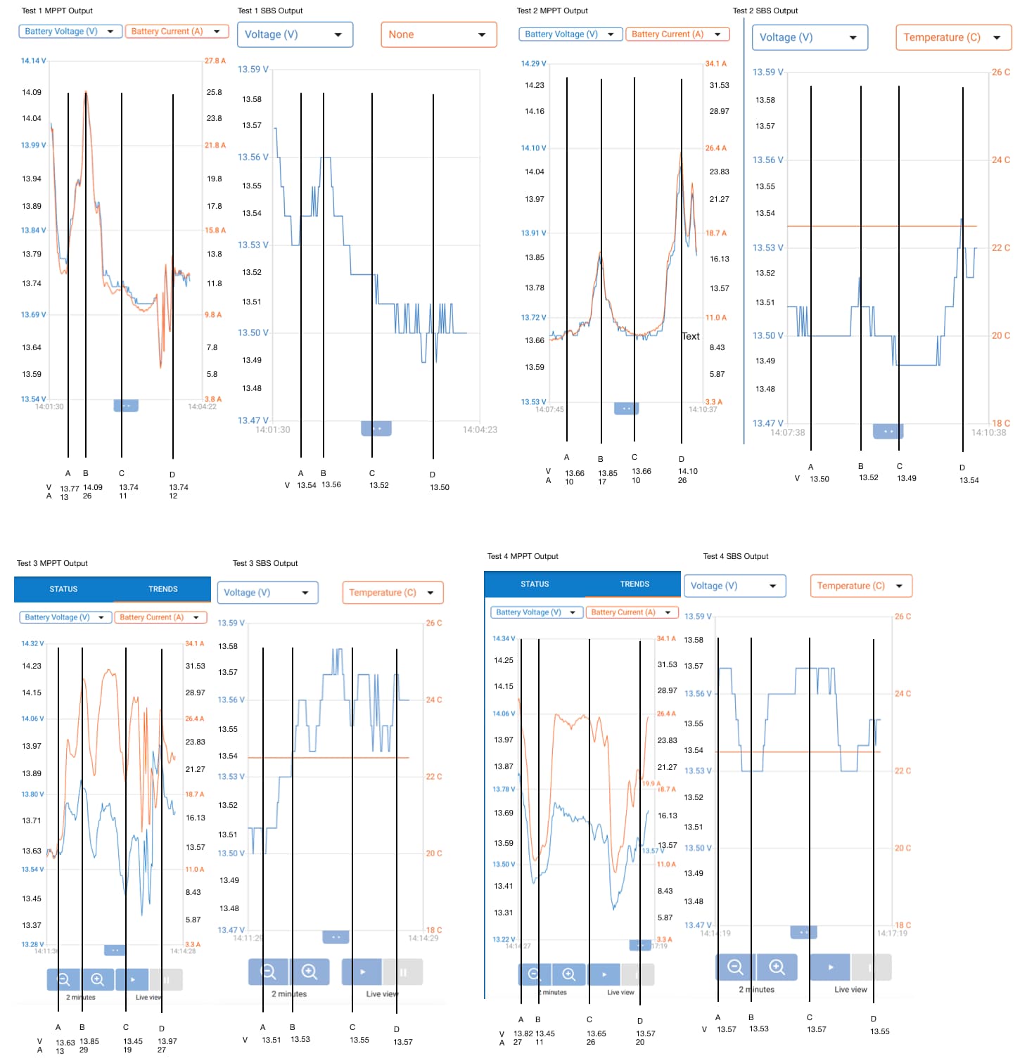
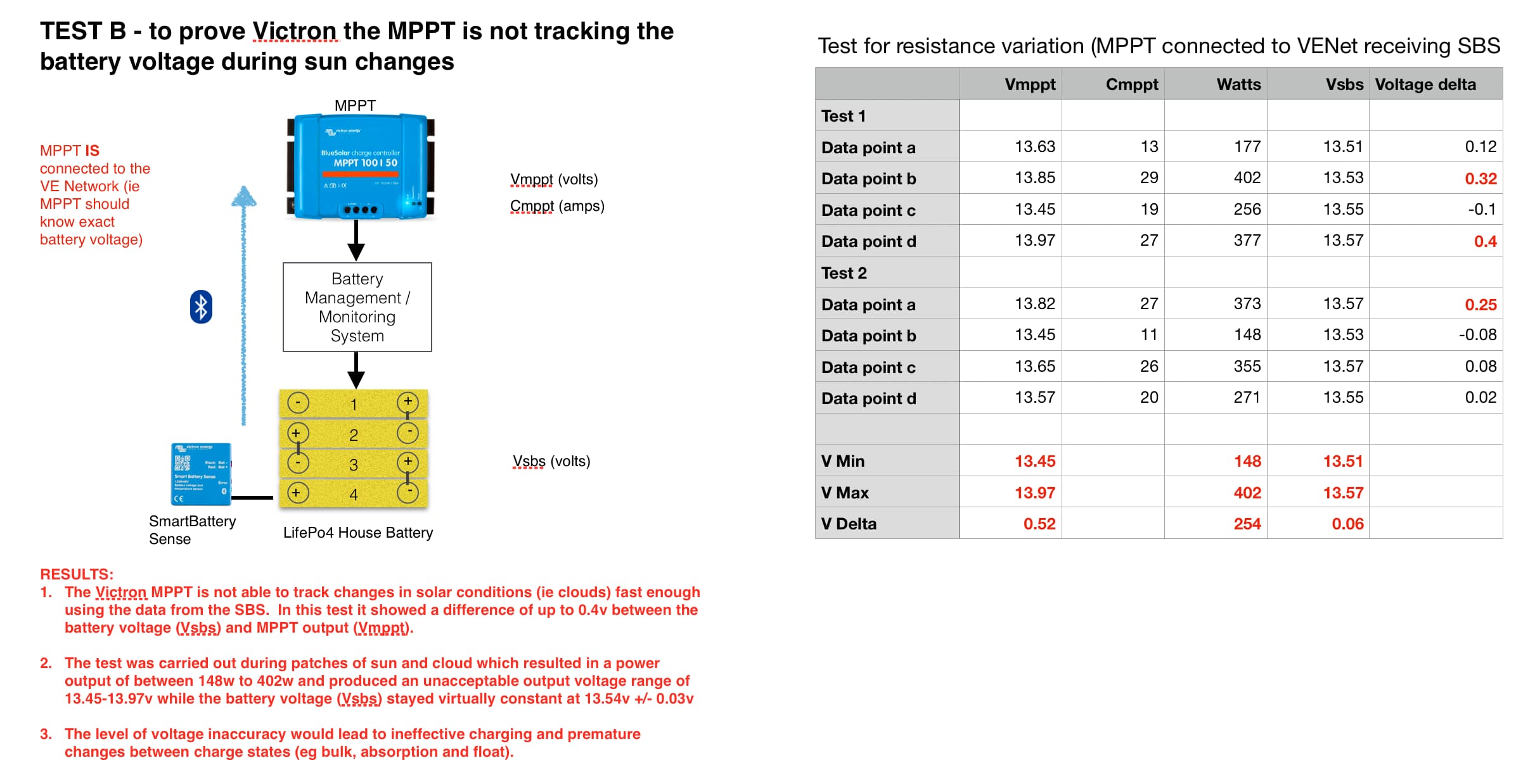
7. The datapoint summaries in the above two images were collected from the raw test graphs that are provided in the following for reference only. The top row is the first test and the bottom row the second. Each row contains two separate runs and output from the MPPT and SBS over the same period. Four data points were collected from each run totalling 16 data points for Voltage at the MPPT (Vmppt), Current ouput (Cmmpt) and voltage at the battery (Vsbs). Many other tests were run that were consistent with the results of these.


8. In summary I do not believe the solar controller with battery sense is capable of measuring voltage accurately in its current implementation under varying light conditions and have provided specific results in red in the first two images.

Thanks for reading


test-a.jpg (229.6 KiB)
test-b.jpg (194.5 KiB)
raw-data.jpg (150.9 KiB)
15 comments
2 |3000

Up to 8 attachments (including images) can be used with a maximum of 190.8 MiB each and 286.6 MiB total.

Mark avatar image Mark โ™ฆโ™ฆ commented ยท

Hi Dean,

It seems that you were busy testing yesterday - nice report.

The independant baseline is good information, as are the recordings with SBS paired.

I agree that the data you provided suggests that an intermittent wiring issue in your setup is unlikely and also that there is a variance/lag between the voltage as reported/used by the MPPT (including compensation/correction from the SBS) and the voltage as reported by the SBS.

My comments are;

1- The examples that you provided are during conditions with rapidly and significantly fluctuating charge current, as the correction is based off voltage delta and has some integrated dampening - in these conditions it seems to not alter the compensation amount fast enough to 'keep up'.

As you would know, if the charge current goes from say 10A to 30A (3x) in an instant (or the same change in reverse), then even with a constant wiring resistance (no intermittent wiring issue) the voltage drop still increases by 3x.

Maybe there is some opportunity to reduce the amount of dampening to increase the voltage correction response speed, but generally these things are done for a good reason and after a lot of testing - so it may have negative repercussions elsewhere. But I will try to find out...

2- The PRIMARY and most IMPORTANT purpose of charge voltage compensation (in relation to the true voltage as measured at the battery terminals) is to ensure that the battery bank receives the correct/accurate CHARGE voltage.

This is specifically when the TARGET/SETPOINT charge voltage has been achieved and is being MAINTAINED. While charging at the correct charge voltage setpoint, the charge current will always inherently be relatively consistent.

It doesn't really matter (in relation to accurate battery charging) if a slightly different voltage is momentarily reported under highly dynamic conditions and when the battery voltage is BELOW the target charge voltage. During this time the MPPT is in 'max power point' mode and trying hard to increase the the battery voltage to the setpoint voltage.

3- Sorry to say but I am still worried about your wiring (and anything along its path, such as the BMS contactor and fusing/circuit breakers), due to the apparent high resistance and voltage drop.

I think that the wiring or something in the circuit is likely undersized or has an issue - it would be good to identify the primary contributor and upgrade/fix it. This IS proportionally related to the behavior you have seen.

Your baseline example shows that you have 0.56v of voltage drop at a charge current of 26A. This means that you would have >1.0v of voltage drop at the full MPPT charge current of 50A... thats over 8% loss for a 12v system... this is huge and potentially unsafe.

If you sort this out then any lag under highly dynamic charge current conditions will be proportionally reduced.

0 Likes 0 ยท
deandavis1 avatar image deandavis1 Mark โ™ฆโ™ฆ commented ยท

Thanks again for your reply. My thoughts on your points as follows:

1. Yes the test was performed over rapid changing sun conditions, but this is real world testing and exactly what happens when the sun goes behind or out from a could.

The whole point of voltage sensing is to calculate the resistance by applying ohms law (V=IR). Once it has established resistance and there is no change there is no need for damping. What you have said implies Victron are deliberately using the voltage value and applying a lag while the constant of resistance is not being used. Monitoring voltage should be done as a final "safety check".

2. "Primary and most important purpose of charge voltage compensation... is to achieve... setpoints..." does not mean the system can be incompetent the rest of the time. Accurate reporting is also necessary and quite frankly the system is failing to properly achieve set points under some real world conditions because of this poor performance. This is exactly the reason I found this problem because I observed the system in float when it shouldn't have been. At this time it spent an hour in float in a day when the batteries only reached 80%. This is unacceptable.

3. I do agree that there is room for improvement to reduce resistance in my installation and this is the topic of my current project. Of which installing Victron charging was the first step. However. you cant argue with the science here. If connections are tight and resistance is constant (which I've proven) then the Victron element is the PRIMARY and most IMPORTANT part of the system failing ;) and needs to be addressed first.

4. (This point not covered in your reply). I have mentioned the following several times to Victron and included it in my results. It would be nice to get Victron's position on this:

"Given the necessity for accurate voltage sensing if Victron are not going to provide a sensor as part of the MPPT controller it has been suggested that the software could be modified to allow for a user input variable of โ€œResistanceโ€ to calculate battery voltage and that โ€œBattery Voltageโ€ is currently an incorrect label and should be changed. Neither of these have been accepted."


I have in past offered my assistance to Victron (@mvader (Victron Energy Staff)) to perform product testing / evaluation which has been rejected. Now I'm finding I'm spending days worth of effort identifying problems like this and, while the quickness of support from Victron has been great, there does seem to be an initial position that there is no problem with the products (as mentioned by other users). It would be good if both of these elements could be reconsidered.

0 Likes 0 ยท
ben avatar image ben โ™ฆ deandavis1 commented ยท

There are a lot of things about your post that I can't quite follow, but I'll make a quick response to your point #1:

It is not true that the point of differential voltage sensing is to "calculate the resistance" and then use that to determine voltage in a static way.

Most real world systems exhibit changing resistance over time, too. Fuses are a classic example: their resistance can change substantially as they heat or cool. They heat or cool based on current and environment.

Also there can be other chargers in the same circuit, each of which can dramatically affect the voltage.

While your particular setup may not have much variation (more on that below), it would not be very useful for the more general scenario to have it static.

In your specific case, I would like to see a video or photo of your physical wiring. This is because in part I don't understand some of the notes in your spreadsheets, but I also want to see the wiring. If you have a way to take some snapshots or post a video, that would be great.


0 Likes 0 ยท
deandavis1 avatar image deandavis1 ben โ™ฆ commented ยท

Ben do you work for Victron?

As you said "there are a lot of things about (my) post that (you) can't quite follow". Mark seems to have a better handle on the situation and I've provided everything to Victron in my post that I intend to or is necessary for them to address this issue.

While there are various components that might exhibit varying resistance at different temperatures I have proven this is not what is going on here with my base line test.

In short I have proven to myself that the Victron system is at fault to and provided this data in raw and interpreted format in good faith to Victron.

Victron have a choice if they would like to address this issue rather than defend it. If they would then I would expect them to establish the same tests posted in this thread and come to their own conclusion.

If this is not fixed then as a consumer I will have to decide if I accept the poor voltage monitoring at the times when I've observed it happening (ie changing light conditions and night time monitoring) or move to a competitors product that I know does not have this problem and I hope this helps other existing and future consumers.

For the record I am observing three systems. Two Victron Installation (mine and and a friends professionally installed) and an Epever installation. Both Victron installations exhibit this problem. Epever does not.

0 Likes 0 ยท
Show more comments
ben avatar image ben โ™ฆ commented ยท

I've commented down-thread on one aspect of your suggestion/concern. And, I'm not here to defend Victron gear or the SBS remote sense implementation in particular. (I also don't have an SBS in my system.)

However, I feel compelled to note that despite your deep dive into the issue(s) you're having, it's still really hard to tell what's going on with the data you've presented.

One thing that makes it tough is that the graphs are not aligned, and it doesn't really even look like you are sampling your data points at identical times. Maybe you are, but it's impossible to tell as shown.

Another thing is that your spreadsheet columns don't match across the scenarios, and it's unclear why you wouldn't make the columns match. I'm not suggesting you're trying to hide something, I just can't follow them very well.

Another issue is that you aren't explicitly describing what mode the MPPT is in in each case. Are we in CC? CV? CV float?

If you're seeing the issues when in CC so far, I'd be very interested in understanding more about what happens when the MPPT is in CV (absorption). I can't see where you've written about this, but it's really important.

Lastly, I would suggest if you're up for it that you make a video of your first, most basic test. No need to do four runs or to do the second test. If I'm understanding your test correctly, it should only take a couple minutes to record a video. If you could show the wiring end to end, and if you could also take a good meter and make some independent readings at the same points (battery terminal, upstream at the BMS, MPPT output terminals) that would help a lot.

I suspect you're seeing an issue with your own setup and not a fundamental flaw in the SBS implementation, but if you have uncovered a real issue, I'm sure Victron will want to know about it and get it squared away. So far, though, it's still too vague to be actionable in my opinion.

0 Likes 0 ยท
klim8skeptic avatar image klim8skeptic โ™ฆ ben โ™ฆ commented ยท

SBS > Mppt test

Short video showing Mppt voltage interaction with SBS.

Bluesolar 75/50, Smartsolar 100/50, both v1.42, networked to SBS.

Phones/tab/computer all on VC 5.11.

300ah Winston cells, 85% Soc, Cloud cover 7/8.

Calculated voltage drop Mppt > batt 0.2v, actual volt drop <0.4v (@50a).

0 Likes 0 ยท
ben avatar image ben โ™ฆ klim8skeptic โ™ฆ commented ยท

Sorry, before I try to interpret this, is this a demonstration of the same problem on another setup, or are you the same guy posting under two different names?

(Do you want to open another Question with your issue, whatever it may be?)

0 Likes 0 ยท
klim8skeptic avatar image klim8skeptic โ™ฆ ben โ™ฆ commented ยท

Hi Ben,

Different user and location.

It is just a short video showing real time (as close as you could get, with app refresh's) interaction between mppt and SBS. The hardware involved is similar and I thought it would be useful. Maybe Dean could post something similar?

It is interesting that the app on the computer mirrored the app on the phone. (100/50 smartsolar)

0 Likes 0 ยท
Show more comments
deandavis1 avatar image deandavis1 ben โ™ฆ commented ยท

Ben, as per a post I just made in another part of this thread, I have waisted as much time as I intend on this and 100% sure Victron have a product problem.

I do not find your comments very helpful and it seems to have gone past a point of defending a product to bordering on trolling.

If you are really questioning my data points or why the first test is designed to check for resistance consistency while the second test is designed to demonstrate the poor voltage tracking of Victron, then I have provided all raw data to do your own calculations. More importantly I've provided the senarios for Victron to set up the necessary test conditions. If Victron would like to continue to denny there is a problem with the product then the best way would be to show their own test under the provided conditions and maybe a video themselves.

I simply do not have time to continue to reiterate the same point or ague etc. I will do the following:

1. Hereby offer Victron the opportunity to come and inspect my installation and allow me to demonstrate the product problem first hand.

2. I will make an offer to a local Electronics Engineer YouTube blogger to make a video on the subject using my equipment that might serve as a resource to consumers and Victron, but doubt he has the time as well. I will also point it out to a couple of overseas bloggers in the slight chance they have the right controller and sensor to make a video.

3. Unless absolutely necessary I'll stop responding here but will send this thread to Victron Management, because I feel this issue (that has been reported by other users and in other threads) is falling on deaf ears.

Finally I would like to express that the format of this forum IMHO makes following the thread overly difficult. I would recommend Victron consider changing to a linear discussion format that allows quoting of previous comments. Something like whirlpool.net is useful.

If Victron would like to shut down this thread then please place this reply as my accepted answer that we agree to disagree or you will address the problem.

Once again my thanks to Mark and my local Victron representative for their efforts and other users who have highlighted this problem.

0 Likes 0 ยท
ben avatar image ben โ™ฆ deandavis1 commented ยท

I'm just trying to help you. But, we're going to agree to disagree, I see.

0 Likes 0 ยท
deandavis1 avatar image deandavis1 ben โ™ฆ commented ยท

Thank you again. I'll leave this with Victron now. As I said I'm not trying to find a problem in my installation but demonstrate an issue with a Victron product and finding your comments in this thread distracting from this partly because as you say you're not following the details.

0 Likes 0 ยท
Show more comments

Related Resources