Is there a manual that spoon feeds you how how to set up the VE bus network? I am not looking to connect to the internet, I just want all my devices to talk to the GX control panel. This shouldn't be as hard as it is, there is a serious lack of information about the nuts and bolts of the process.
asked
Manual for VEbus connection
Hi @Bdkw1,
It can be confusing the first time through; there are SO MANY possible configurations.
Here are a couple of links that help to explain the situation;
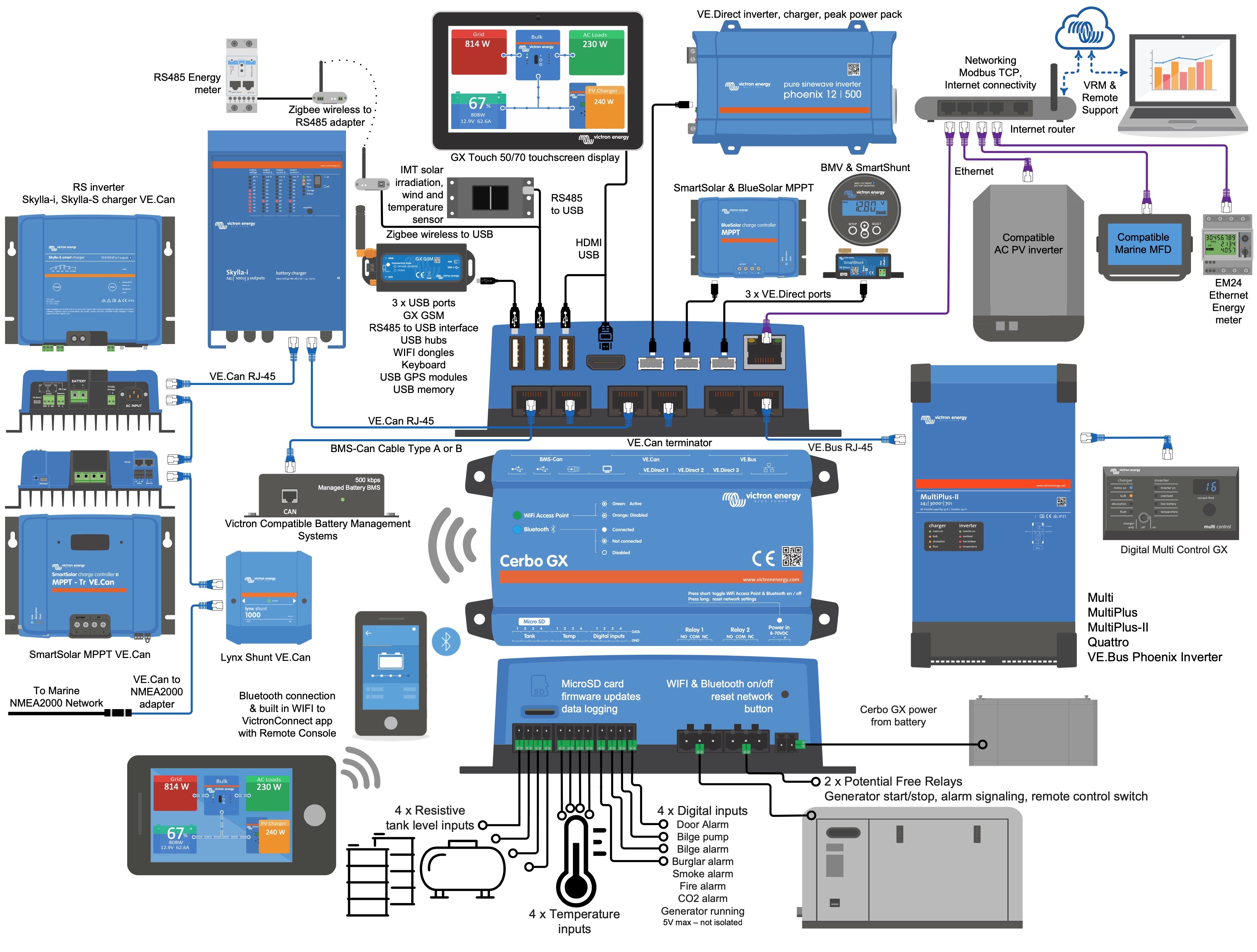
https://www.victronenergy.com/media/pg/Cerbo_GX/en/installation.html
https://www.victronenergy.com/media/pg/Cerbo_GX/en/connecting-victron-products.html
The short story is that the only VE.Bus compatible products are the VE.Bus Inverter/chargers and their accessories (like the digital multi control)
Solar chargers use a different interface called VE.Can or VE.Direct, depending on the model.
It would be nice if everything was simpler, and we are trying to make new products as simple to understand as possible, for now it does take some time to research.
VE.Bus is a closed network. No devices other than Victron inverter/chargers, inverters and the GX family of control systems can connect to this bus. The reason given by Victron (and which makes sense to me) is that the traffic between the various devices is extremely time-critical in that it synchronizes parallel and multi-phase systems. Failure in this synchronization due to unregulated traffic could be nasty. (my words).
The correct way to do what I think what you want is to include a GX device in the system and use that for control and status via ethernet. There are many different protocols which can provide this: modbus, NEMA-2000 (Canbus), MQTT (which is used by Victron's VRM). You can even run NodeRed and SignalK for expanding the functionality of the GX and connected devices.
I have all victron equipment.
It would be good to know WHAT Victron components you have.
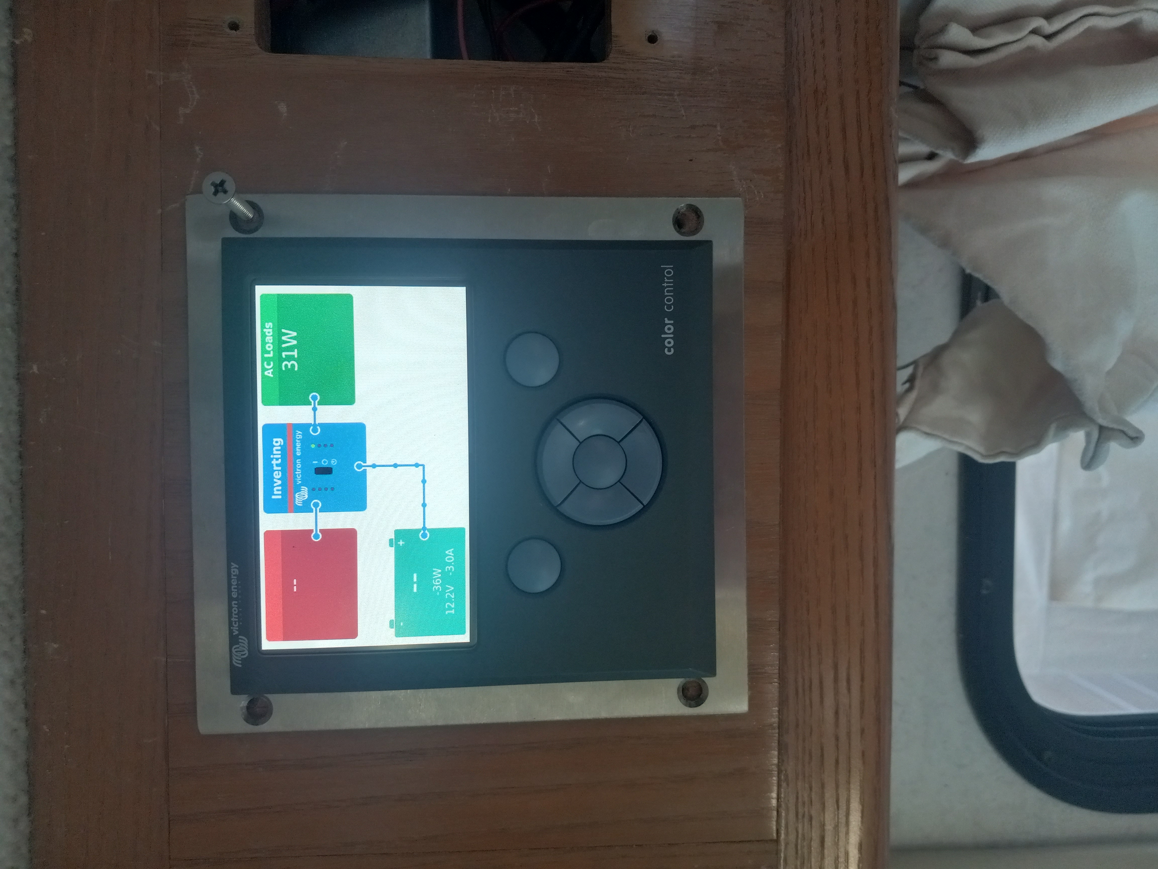
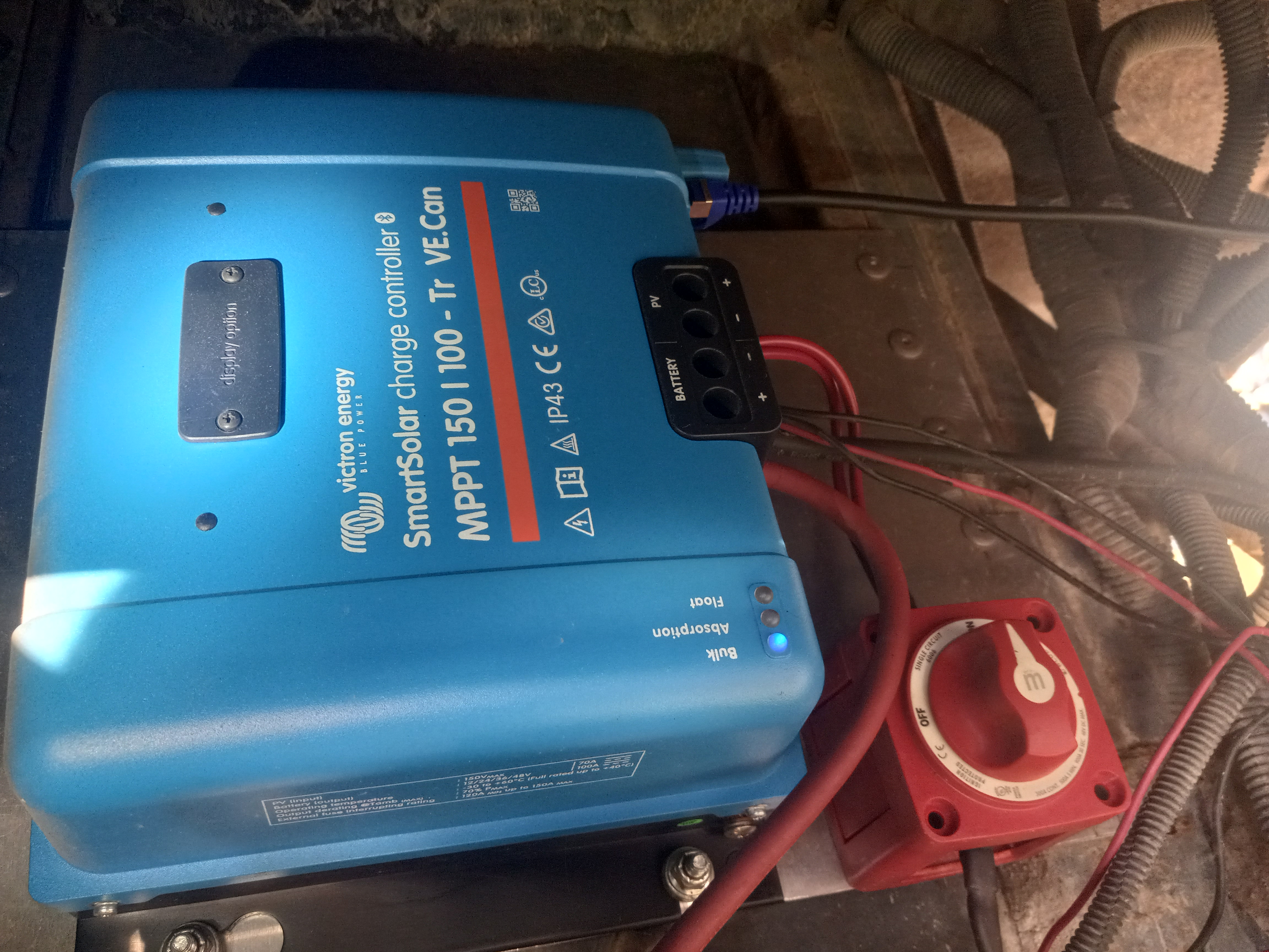
I have the gx control panel, a multiplus2, smart solar 150/100 gx140 and a very smarts bus diongle. This is a motorhome install.
When I started it was just the solar an the inverter. The dongle allowed coms with the inverter, solar charger has built in bt. Due to the location of the solar charger, bt wouldn't reach it unless you were standing behind the coach. So I wanted to add the control panel and tank monitor to fix the non op tank gauges. Ran network cable to the multiplus then on to the charger. Terminator plugged into the charger and the GX. All I can see is the multiplus, no solar or tanks. Is there something I need to configure on the GX? How would one go about doing this. There is almost zero documentation in the manuals on how to set this up. But there are 5 different vids on how to connect to the internet......
You need to be more accurate about the components you have.
Write down the exact name or make pictures.
My guess is you mixed up VE.Bus and VE.Can.
The manual of each device should show exactly how you have to wire it.
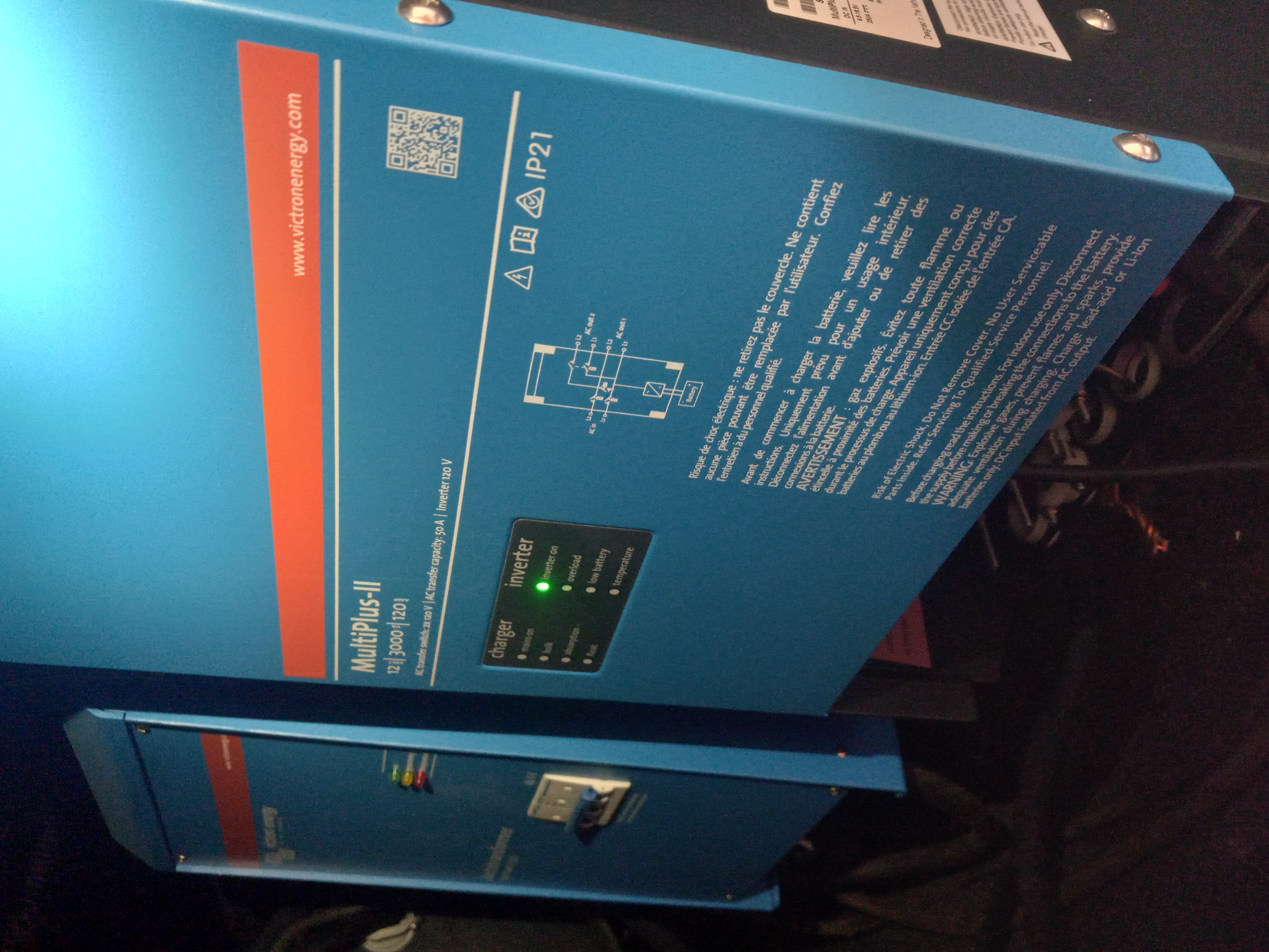
Ok, this is what I am trying to hook together. As I understand it, the is no way to make the charger talk to the inverter directly. They must both be on separate cables attached to the control panel. Running the first network cable involved removing large portions on interior, crawling under the coach to install conduit and drilling numerous holes. Unfortunately the conduit is only large enough for 1 cable. You can see how I don't want to redo all this as I'm not sure I can fit another cable through some spots.
How about a firmware update to make the charger VEbus compatible? Or make the inverter CAN compatible? You know, common platform......
I would suggest the following:
1. Read Wiring Unlimited available free here: https://www.victronenergy.com/blog/2019/09/03/wiring-unlimited/
Also read the manuals that came with your components. It's all plug and play but one has to understand why things are done in a certain way to avoid problems down the line. Wiring Unlimited has many valuable examples, explanations, best practices and drawings. For example, see page 40.
2. There are many schematics here: https://www.victronenergy.com/support-and-downloads
Choose what applies to you.
3. Wire your components accordingly.
4. If you run into issues, seek help from the forum.
F.
I think you may be confusing several of the different interconnects used in a Victron. VE.Bus, VE.Can, and standard ethernet all use RJ-45 connectors but are different protocols and physical interfaces. There is also VE.Direct which uses a 4-pin connector. Refer to:
https://www.victronenergy.com/upload/documents/Technical-Information-Data-communication-with-Victron-Energy-products_EN.pdf
Some solar controllers have VE.Can connections but these can not be connected to a VE.Bus device.
A GX device (Cerbo, Ekrano, etc) provides for connection of nearly all Victron devices and has ethernet, USB, VE.Bus, VE.Can and VE.Direct ports.
Victron sells converters for VE.Bus and VE.Direct to USB which allows attaching these devices to say a Raspberry PI running Venus OS firmware, or to expand a GX device's capabilities.
Many CANbus to USB adapters are available which can add additional VE.Can ports to a GX device.
RS-485 to USB adapters are also available to integrate say Modbus devices into a victron system when those devices don't support Modbus TCP
Ok, I finally got my head wedged in the engine compartment far enough to read the bottom of the solar charger. You are correct, it's regular can. So I cannot daisy chain it with the inverter which is VEbus only. Highly inconvenient. I need to run a separate cable the entire length of the coach or live in ignorance. Now on to the tank monitor issues.
You know, I bought all the equipment from one manufacturer to avoid headaches like this. You would think this would be plug and play......
The fact that nobody has mentioned a network setup guide/tutorial says volumes. Lots of marketing, very little actual info.
It is more or less plug and play you just need to connect it together correctly.
And if you read the manuals of your devices you get all information you need to do it correctly.
I have read all the manuals, it just says plug it in and it magically works. Or not. The real issue is when it's installed and you can't see the labeling on the plugs. That and every piece of equipment has a different com cable. Some standardization would be really nice. Either stick with can or stick with VE bus. Right now there are 4 different connection methods.
@Bdkw1
It depends on what you have. Some of the things you mentioned do not exist. It's plug and play if you have the right equipment. Provide accurate descriptions or pics as others have mentioned.
F.
This is the main issue. Every component hooks up a different way. In my mind, a network is everything hooked together. This requires a separate cable for each component to the control panel. This is very inefficient and time consuming. If I had known this before hand, I would have skipped the price premium and gone with different equipment.
Ve bus 'network' no explanation needed.
If it is labelled ve bus on the port (only found in the inverter) connect it to the VE bus port on the GX. Done. Plug and play. Use a straight cable.
If you are using more than one inverter, then I suggest you get some training or professional help.
You make it difficult to help you when you don't answer the questions, don't read the manuals and then provide pictures which don't fully answer the questions.
The ports are all labelled. Both on the device and in the manuals.
Connect each device once to the same port type on the GX.
Both VE.Bus and VE.Can can be daisy chained. That's why there are two ports on each device.
Use the supplied terminators at each end of the daisy chain.
Don't interconnect VE.Can and VE.Bus.
You probably don't need VE.Bus, but we're guessing as we don't know what's installed.
Don't create a smart network as you're going to use cables.
Use good quality cables.
There are good reasons for the different connection methods. Pointless to try and explain it here. I'll just say that Victron is used in many different ways outside of what you appear to need to do.