question

sharpener avatar image
sharpener asked

MPII - contact closure on mains fail?

I have a 5k MPII GX which I use in ESS mode to supply the whole house.

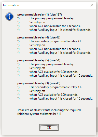
Is there an aux output which I can programme so as to get a contact closure when the mains fails, in order to shut down a big load and conserve the battery?

I don't want to wire the load to AC-Out 2 as AFAIK it is not then possible to override it, whereas I could put a manual override switch in series with the shutdown contacts.

I know I can fit an external relay on AC-Out 2 but thought I would ask before buying one.

Multiplus-II
2 |3000

Up to 8 attachments (including images) can be used with a maximum of 190.8 MiB each and 286.6 MiB total.

6 Answers
nickdb avatar image
nickdb answered ·

I find the best way is to use smart timers, plug sockets, switches and manipulate them via node red.

Allows for more flexible control.

Most of these are wifi based and have an API or node that allows access.

I have full control of geysers, heat pumps, lights etc.

2 |3000

Up to 8 attachments (including images) can be used with a maximum of 190.8 MiB each and 286.6 MiB total.

sharpener avatar image
sharpener answered ·

I am trying to establish if I already have the necessary nutcracker. Maybe Assistants will do it?

No wish to go down the sledgehammer route if I can avoid it.

1 comment
2 |3000

Up to 8 attachments (including images) can be used with a maximum of 190.8 MiB each and 286.6 MiB total.

nickdb avatar image nickdb ♦♦ commented ·
Its more like that little hammer from the shawshank redemption. But it does require a fair amount of tapping;)
0 Likes 0 ·
duivert avatar image
duivert answered ·

you can use the programmable relay for that, but there has to be a relay in between for the big load (use the mp2 relay to switch a bigger relay for the load)

us the programmable relay assistant in ve config to set this up

2 |3000

Up to 8 attachments (including images) can be used with a maximum of 190.8 MiB each and 286.6 MiB total.

sharpener avatar image
sharpener answered ·

Thanks. It is for a heat pump which requires a low current voltage-free input to turn it off. From the data sheet the Multi's Aux contacts will carry 4A up to 35V DC which will surely be enough for a control signal.

Have found this answer from @Jason - UK which seems to fit the bill exactly, unless further refinements are possible?

1 comment
2 |3000

Up to 8 attachments (including images) can be used with a maximum of 190.8 MiB each and 286.6 MiB total.

Jason - UK avatar image Jason - UK commented ·
@sharpener If the 4A limit is insufficient, you can always fit a relay in-between, but yes, it has been sufficient for what I use it for. :-)
0 Likes 0 ·
sharpener avatar image
sharpener answered ·

@Jason - UK as you are doing something similar, what do you think of the following scheme of Assistants? I am struggling to incorporate a memory function. Does the s/w continuously run through all the assistants in order, or what?

  1. Close primary relay if AC input not available for 1 second - shuts down HP automatically on mains fail
  2. Open primary relay if AC input available again for 60 s - restarts HP
  3. Close primary relay also if momentary contact across Aux1 for 3 s - manual push-to-stop HP. How to give this priority over #2?
  4. Open primary relay if momentary contact across Aux1 for 10 s - manual override to #1. to restart HP after turning on noise reduction/low power. How to give this priority over #1?

If I can get this right then I will also use the K1 output similarly to light a 12V warning light.

Not sure if you are allowed 8 Assistants or whether I have got the order right?

TIA

1 comment
2 |3000

Up to 8 attachments (including images) can be used with a maximum of 190.8 MiB each and 286.6 MiB total.

JohnC avatar image JohnC ♦ commented ·
@sharpener

It's possible to do this using ACOut2. Manual override via Aux port, which can be read by Assistants and incorporated into the logic string.

And yes, Assistants at least seem to be read continuously. They don't get executed as they're read, just the end result. Must be in the right order. I find them fun, a mind challenge.. Have a go.

I don't know the limit to the number of them, but expect it's quite high.

0 Likes 0 ·
sharpener avatar image
sharpener answered ·

Thanks. Do you know @JohnC if the manual override can switch AC-Out 2 back on if it has been turned off by a mains outage? This was my first thought, but using the control input on the HP seems more elegant than cutting the power.

Realised you can have two triggers attached to one Assistant so need only four, will try the following (K1 is open collector o/p so ideal for driving indicator lamp and/or acoustic alarm).

It might need a Relay Lock Assistant in the middle of the sequence to give 5 mins minimum off time for the HP unless overridden by pushbutton.

1710237526957.png

Yes, it seems from what I have read the Assistants get evaluated in sequence then the result is implemented, as you imply @JohnC. I have no idea how often this process repeats or what conditions trigger it, it would be nice to know but it seems it is not well documented. Presumably the countdown timers are all reset when the output changes state but who really knows?


1710237526957.png (30.7 KiB)
4 comments
2 |3000

Up to 8 attachments (including images) can be used with a maximum of 190.8 MiB each and 286.6 MiB total.

JohnC avatar image JohnC ♦ commented ·
@sharpener

I think you're right about the 'more elegant' solution.

I find it difficult to describe how Assistants work, but you can pretty much do anything with them if you have the necessary input/output relays and the data points to work from. Best to check first that the relays work with the hardware as you expect.

Just start simple and build up any extra stuff as you go. The indicator light set up early should help you see what's happening. You'll learn by doing it, although there's an Assistants training module on Victron Professional you could take a look at.

Thinking out the logic order is the tough part, but the sense of achievement at the end is worth it. Have a go.. Good luck..

0 Likes 0 ·
sharpener avatar image sharpener JohnC ♦ commented ·

<You'll learn by doing it, although there's an Assistants training module on Victron Professional you could take a look at.>

Have done that module, it sheds no light on the interaction between multiple assistants, and how frequently they get evaluated. Have gleaned a bit from looking at a number of questions on here but the answers are mostly of the form "suck it and see". Having done a lot of deterministic programming from the Elliott 803 onwards it all seems a bit hit and miss.

Also don't want to have to do a lot of experimentation involving isolating AC In to the whole inverter, as it will hammer the relays and if it goes wrong the house supply gets cut off. I suppose I can simulate this to begin with by using Aux 2 input as a proxy for mains failure.


Edit: @Jason - UK points out in this thread that the Aux 1 input is allocated by default to Disable Feed-in(!).

Perhaps @Guy Stewart (Victron Community Manager) would comment on why this option is ticked by default, especially as it reportedly needs an unlock code to get back into this screen to clear the box.

1710261695100.png

0 Likes 0 ·
1710261695100.png (45.5 KiB)
Jason - UK avatar image Jason - UK commented ·
@sharpener @JohnC

One thing to note, you want to end the demand signal on the heat pump using the relay, not kill the power supply. If a compressor is on a full load and you kill the power to the heat pump, you reduce its life expectancy as compressors need to spin down in a controlled manner to reduce wear on the internals. I've seen my Mitsubishi Ecodan unit over run by 11 minutes before after ending demand. Anyone with a CO2 heat pump has a minimum compressor run time so even more critical. Some manufacturers of the R290 heat pumps also have a minimum compressor run time as well.

0 Likes 0 ·
sharpener avatar image sharpener Jason - UK commented ·
Thanks. Yes the Vaillant Arotherm Plus (R290) specifies a 3 - 4 min minimum run time. It also has provision for separate 230V control power and interruptible 230V main power to the outdoor unit, this is to allow the German utilities to shut down the interruptible supply when they are load shedding (I assume this is by ripple control or similar). So I suppose it is forseen in the design that power interruptions might happen.


However since they also provide a 2-wire ESCO control input to achieve the same end this is a lot neater as it can be driven from the MPII relay output and so avoid me having to move its 4 sq mm supply connection over to AC-Out2.

0 Likes 0 ·