question

mike-donahue avatar image
mike-donahue asked

Issues connecting 8-relay I2C to a RPi4 running Venus 3.12

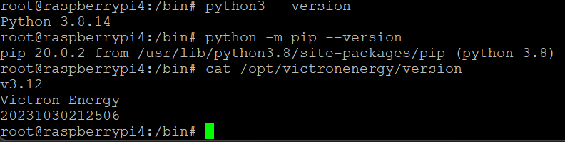
Howdy, I’m running a RPi4 with Venus 3.12 and am having serious problems with the i2c bus.

Already installed are 6 relays using the GPIO bus. They work great but I wanted to move some of the scheduled/programmed relays from the GPIO bus to the i2c board and use the first six as manual switch via the touchscreen.

1708630843731.png

I’m trying to utilize these 8 relays via NodeRed. https://www.amazon.com/gp/product/B083LFPCK8/

Things are somewhat checking out but still haven’t found any real detailed documentation/forums.


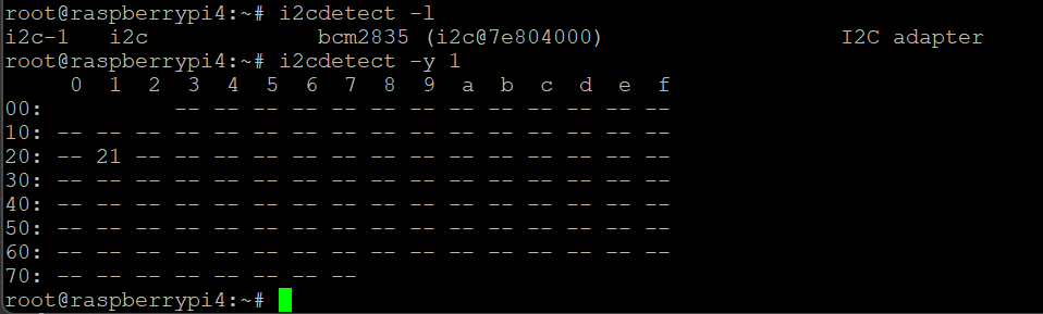
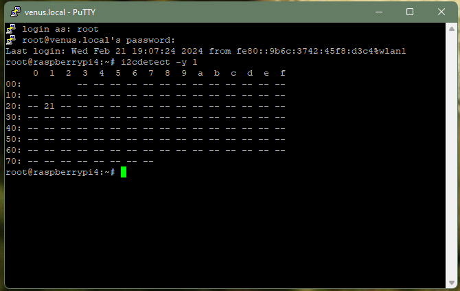
“i2cdetect -y 1” via Putty - Device ID: 21

1708630828974.png

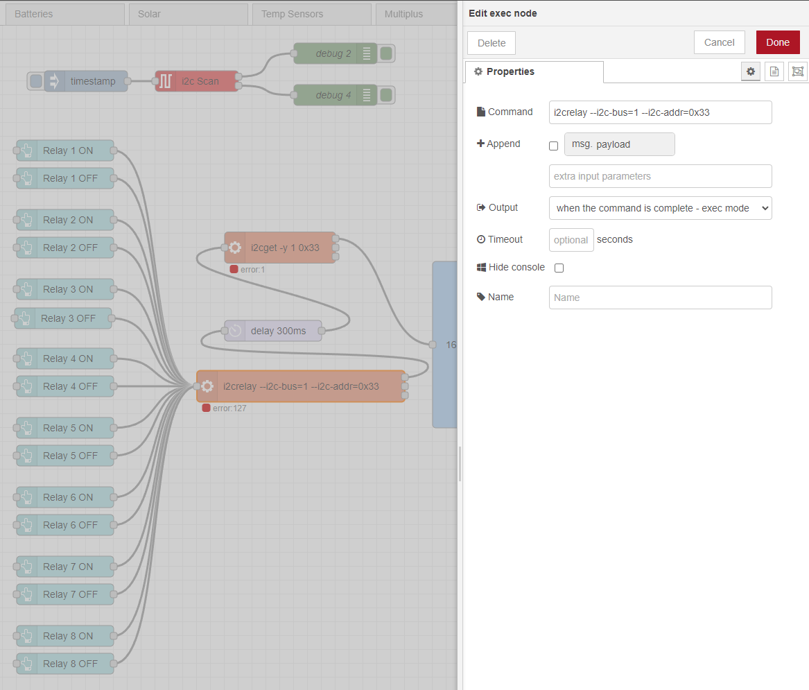
“I2c Scan” Node - Device ID: 33


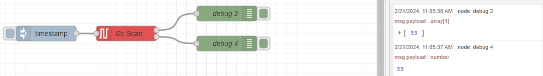
Which address is correct?

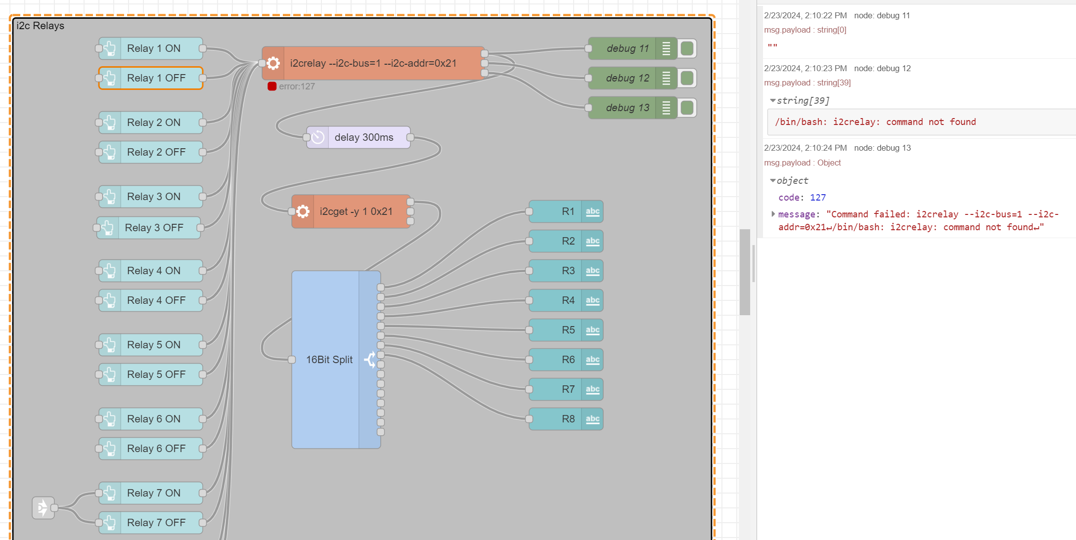
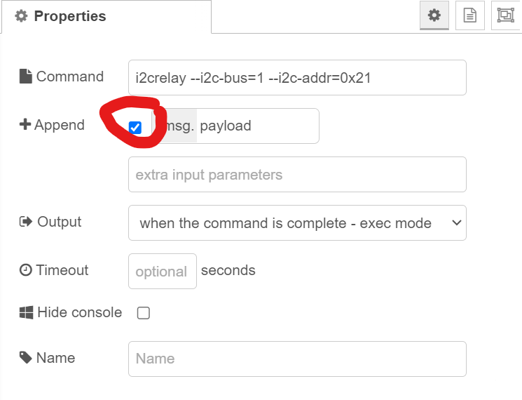
For Node-Red I use these two pallet node groups. I’ve tried a few others but with such limited documentation of i2c/nodered/venus I’ve come to a standstill. These are the nodes I'm using…

-Node-red-contrib-i2c

-Node-red-contrib-sm-8relind

Both have turned on random relays but nothing straightforward. i2c logic is at 3.3 volts.

I’m trying everything I can think of but only have been able to turn the relays ON and not the right ones. So they are all ON right now.

8 relays. https://www.amazon.com/gp/product/B083LFPCK8/

I’ve read the relays might be backward so I’ve tried 00 and FF to get some activity. Some turn on but I’ve never been able to turn any off. I’ve changed the jumper on the board but saw the same scenario; i2cdetect and ‘I2c Scan’ still reported different addresses.

Does anyone have any example flows of an i2c relay board in Victron Venus OS? I can learn, I’m just seriously striking out on any documentation. Any links that I can explore would be amazing. I've learned on how the i2c bus works but nothing is making sense. Should I go to Fiverr? haha

These are some of the links I’ve been using.

https://community.victronenergy.com/questions/196633/how-to-activate-i2c-bus-and-use-it-in-node-red.html

https://github.com/fivdi/i2c-bus/blob/master/doc/raspberry-pi-i2c.md

https://github.com/fivdi/i2c-bus/issues/36


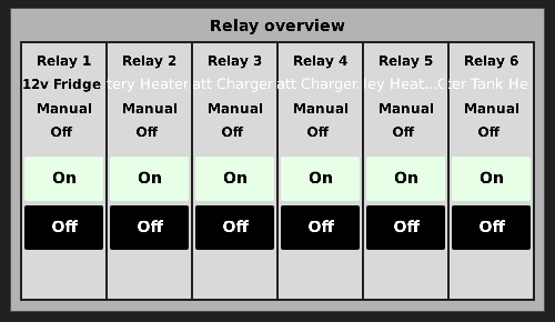
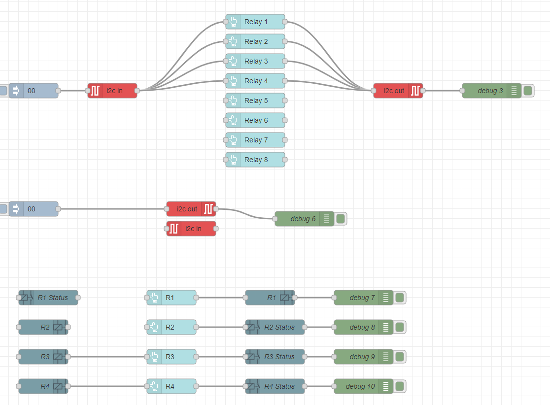
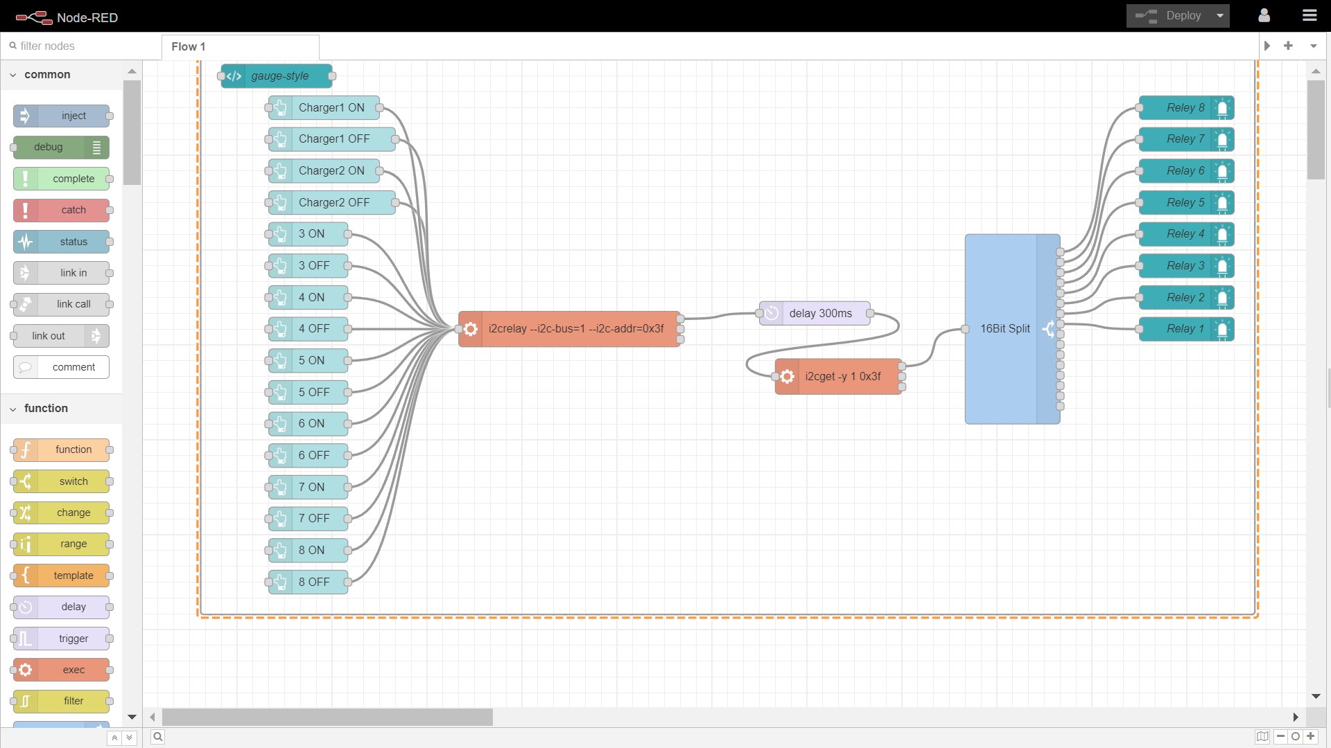
This is my sandbox in NodeRed
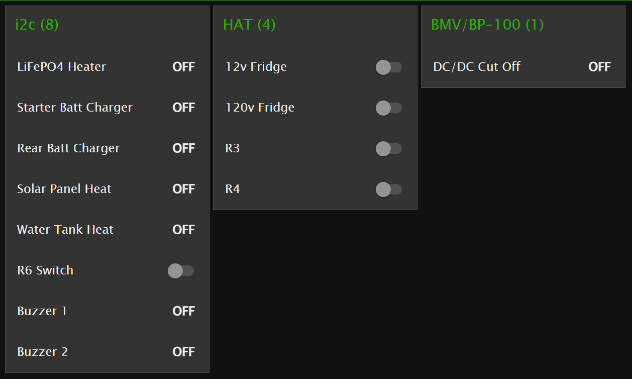


Node-RED
1708630348986.png (35.7 KiB)
1708630828974.png (35.7 KiB)
1708630843731.png (13.2 KiB)
2 |3000

Up to 8 attachments (including images) can be used with a maximum of 190.8 MiB each and 286.6 MiB total.

3 Answers
johnny-brusevold avatar image
johnny-brusevold answered ·

@Mike Donahue

I haven't had any problems getting it to work, but I'm using the python library for controlling the same card you have.

Sorry but I can't share the node-red dashboard code.

2024-02-22.png


The first button only sends msg.payload '8:on' for relay 1 (inverted relay)


The next button for relay 1 msg.payload '8:off'


this is passed on to the python command with exec node 'i2crelay --i2c-bus=1 --i2c-addr=0x3f'


added a delay and a 16 bit split node to read state on the relays.


That's all


2024-02-22.png (219.3 KiB)
1 comment
2 |3000

Up to 8 attachments (including images) can be used with a maximum of 190.8 MiB each and 286.6 MiB total.

mike-donahue avatar image mike-donahue commented ·

Thanks! This helps. I've replicated the flow on my end but I'm not sure of some of the attributes that would be in the code.

1708711460336.png

Any other help would be great! Thank you!

0 Likes 0 ·
1708711460336.png (118.9 KiB)
johnny-brusevold avatar image
johnny-brusevold answered ·

As you can see here, the i2c relay card is up and running at address 3f

the UU at adress 68 is the I2C real time clock

root@raspberrypi4:~# i2cdetect -y 1

     0  1  2  3  4  5  6  7  8  9  a  b  c  d  e  f
00:          -- -- -- -- -- -- -- -- -- -- -- -- --
10: -- -- -- -- -- -- -- -- -- -- -- -- -- -- -- --
20: -- -- -- -- -- -- -- -- -- -- -- -- -- -- -- --
30: -- -- -- -- -- -- -- -- -- -- -- -- -- -- -- 3f
40: -- -- -- -- -- -- -- -- -- -- -- -- -- -- -- --
50: -- -- -- -- -- -- -- -- -- -- -- -- -- -- -- --
60: -- -- -- -- -- -- -- -- UU -- -- -- -- -- -- --
70: -- -- -- -- -- -- -- --


So the command to turn the relay on or off from the command line is then

i2crelay --i2c-bus=1 --i2c-addr=0x3f 8:on
root@raspberrypi4:~# i2cget -y 1 0x3f
0x7f


root@raspberrypi4:~# i2crelay --i2c-bus=1 --i2c-addr=0x3f 8:off
root@raspberrypi4:~# i2cget -y 1 0x3f
0xff


the hex value from i2cget is decoded with 16bit split node to give the number from 1 to 8


2 comments
2 |3000

Up to 8 attachments (including images) can be used with a maximum of 190.8 MiB each and 286.6 MiB total.

mike-donahue avatar image mike-donahue commented ·

Awesome! I feel like I'm making some progress. It looks I don't have "i2crelay" installed. I've tried to install it but have had no luck. "i2cdetect" and "i2cget" work fine its just the extra "i2crelay" to finish the flow. Would this be a package to install via the CLI or accessing venus.local / touchscreen?

1708885365427.png

1708885289348.png

I also don't have the UU address anywhere. That might cause problems?

Thank you!!!

0 Likes 0 ·
1708885289348.png (320.0 KiB)
1708885365427.png (18.2 KiB)
mike-donahue avatar image mike-donahue mike-donahue commented ·

I also have Python installed...

1708894664001.png

I followed this thread

I guess I need to find the "opkg" command to install i2crelay. The "pip" command is saying its not found. Maybe I could just copy the files to "install" i2crelay. Thanks again!

0 Likes 0 ·
1708894664001.png (18.8 KiB)
johnny-brusevold avatar image
johnny-brusevold answered ·

I don't remember exactly how, since it's been a long time since I installed this, but have some lines from bash_history that might help.


/opt/victronenergy/swupdate-scripts/set-feed.sh release
opkg update
opkg install git
git clone -b master --single-branch https://github.com/oweidner/i2crelay.git
opkg install python3-pip-dev
opkg install python3-dev
cd i2crelay/
pip3 install --upgrade .

don't forget the dot at the end of the last line


nano /etc/modules

add to file

# /etc/modules: kernel modules to load at boot time
i2c-dev


nano /etc/udev/rules.d/99-i2c.rules

add to file

SUBSYSTEM=="i2c-dev", MODE="0666"
2 comments
2 |3000

Up to 8 attachments (including images) can be used with a maximum of 190.8 MiB each and 286.6 MiB total.

mike-donahue avatar image mike-donahue commented ·

Wow! Thank you. That all worked. I was literally trying to find "opkg install git". And thanks for note about the "."

Thankfully I already did the modules file and the 99-12c.rules file modifications.

Now its on to the flow!

0 Likes 0 ·
mike-donahue avatar image mike-donahue mike-donahue commented ·

If anyone else trying to learn from this thread, the last bit that got me stuck was also very simple.

Checking the Append box is a must. I didn't see it initially and obviously was getting no results.

1709754952426.png


The second issue was the names of the relays were in reverse. 1=8, 2=7, 3=6 and so on.

I physically labeled the relays on the board backward so that the code can still resemble 1=1, 2=2, 3=3 and so on.

All is working great now!

My system is a Raspberry Pi 4 running Venus 3.2 and has a 4 relay GPIO hat (for touchscreen on/off) and an 8 relay i2c board (only programmable from Node-Red).

1709755562252.png

0 Likes 0 ·
1709754952426.png (40.8 KiB)
1709755562252.png (52.6 KiB)