question

John Dent avatar image
John Dent asked

AC screw connection torque for Mutltiplus-II 5000

Are there any torque maximum or recommended values for the AC screw/clamp connectors on a Multiplus-II 5000? (Actually I have the GX version, but I presume it is the same hardware as the non-GX.)

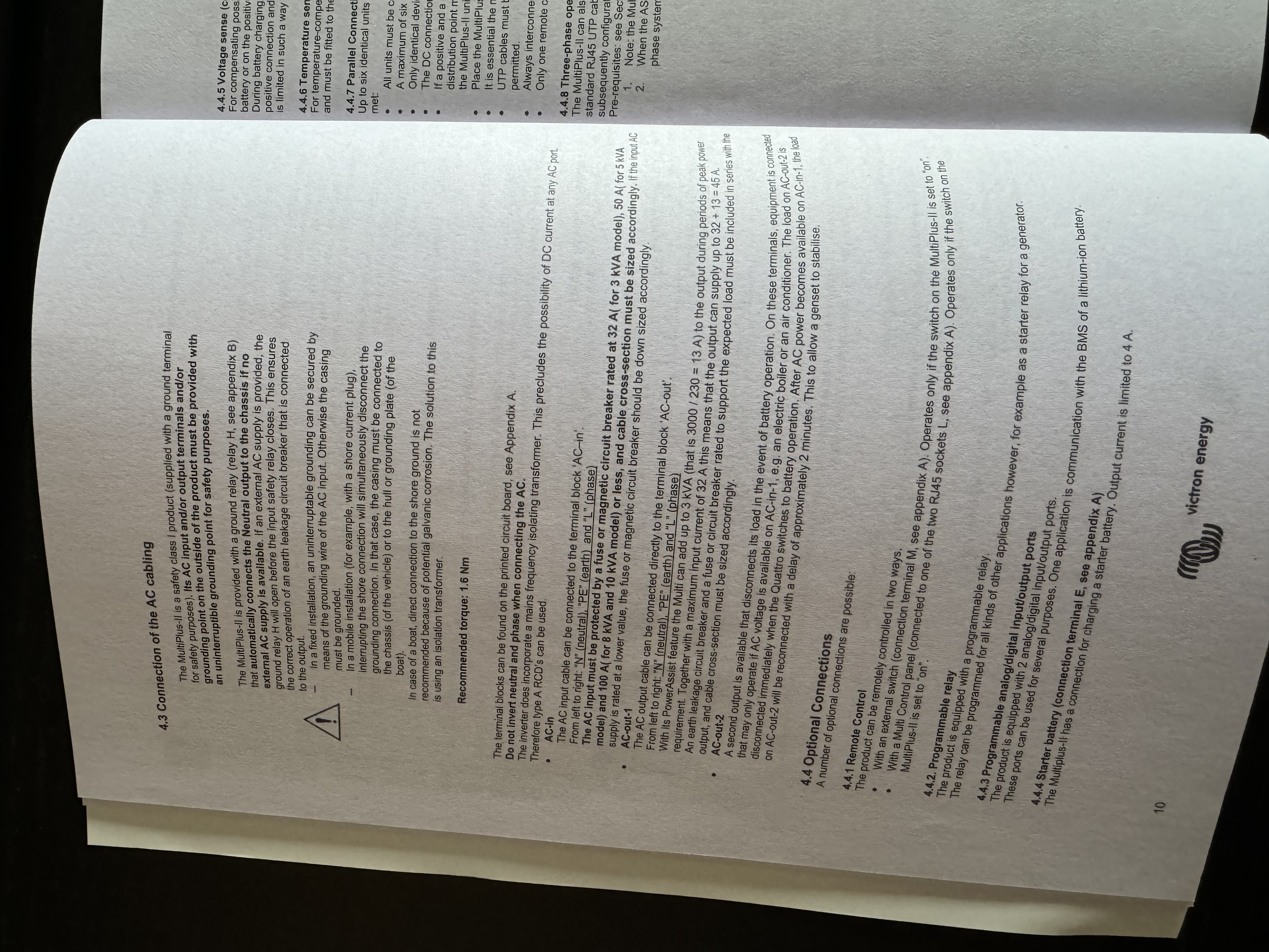
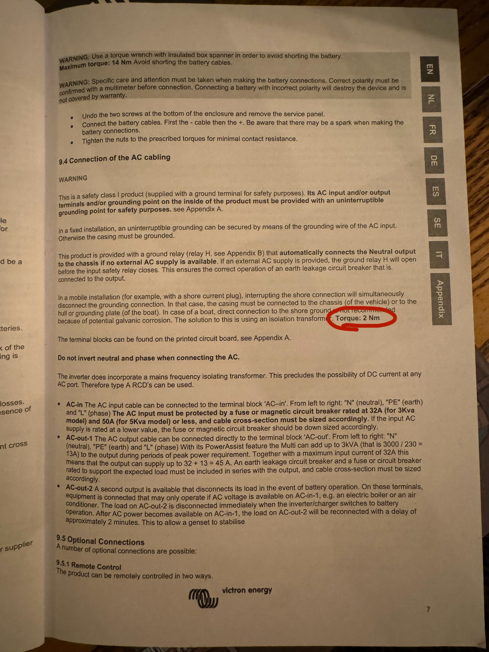
The DC connections are specified — great stuff. But that AC connections not.

I've seen 1.5 Nm mentioned, but this seems incredibly low. Can it really be correct?

There are a few posts already asking around this topic, but no definitive answers. So asking agin in case it bumps the stats.

FWIW, and to add information, it seems (in the UK) that some 45A cooker switches are recommending 2.5Nm. That seems a reasonable equivalent in terms of power, although typically they would be connecting cable with fewer strands. Unless I hear different, this is what I will gingerly use as an ideal.

Related posts: https://community.victronenergy.com/questions/165150/torque-specs-for-ac-connectors-multiplus-ii-10000.html, https://community.victronenergy.com/questions/228589/torque-of-the-clamps-screw-connections.html.

Multiplus-IIac
2 |3000

Up to 8 attachments (including images) can be used with a maximum of 190.8 MiB each and 286.6 MiB total.

7 Answers
beat avatar image
beat answered ·

@denty I agree with you that just applying a 1.5 Nm torque looks too little.

But with practice I discovered that the effect of a torque applied to a screw clamping a wire changes drastically if you only turn the screw, or you also very firmly push it with the torque-limiting screwdriver while turning... It improves drastically the grip on the wire, drastically helping squeeze the wires, while sparing the screw.

A firm push while turning at up to 1.5 Nm has way more effect than turning up to 2.5 Nm with only a small push (except that at 2.5 Nm you don't have a choice than to push firmer to not damage the screw head).

So, yes 1.5 Nm turn without a firm push is sure not enough for a 10 or 16 mm² 40/50A wire, but 1.5 Nm turn with a firm push looks quite ok to me, even with the maximum 16 mm² crimped fine stranded wires.

Also If you have a wire with a few twisted large strands, make sure to untwist them, so they insert parallel for maximal contact area and a firm grip of all strands.

@Guy Stewart (Victron Community Manager) @mvader (Victron Energy) those 2 practician hints might be something for the manuals and your excellent wiring book. ;-)

2 |3000

Up to 8 attachments (including images) can be used with a maximum of 190.8 MiB each and 286.6 MiB total.

John Dent avatar image
John Dent answered ·

I see. That makes sense. I didn't yet look at how the screw clamps work in the Multiplus. I'll take a look with an iPhone and close lens. But if it's as you suggest — that the screw clamp acts to provide downward pressure — then that could be a quite helpful trick.

2 |3000

Up to 8 attachments (including images) can be used with a maximum of 190.8 MiB each and 286.6 MiB total.

Craig Chamberlain avatar image
Craig Chamberlain answered ·

I’m pretty sure it says 1.6NM in my printed Multiplus-II installation manual. Not much different to the 1.5NM you suggest. I’ve also seen pictures where people have broken the AC connector blocks off the PCB so don’t go crazy.

As another data point, the RCBOs on my consumer unit specify 1.2NM for the line and neutral connections, even on 40A shower and cooker circuits.

HTH

2 |3000

Up to 8 attachments (including images) can be used with a maximum of 190.8 MiB each and 286.6 MiB total.

John Dent avatar image
John Dent answered ·

Thanks Craig.

OK. Maybe the 1.5Nm is more appropriate than I presumed. It’s reassuring to find it referenced elsewhere.

I’ll err on the more conservative side then.

2 |3000

Up to 8 attachments (including images) can be used with a maximum of 190.8 MiB each and 286.6 MiB total.

beat avatar image
beat answered ·

It's indeed 1.6 Nm, specified in the manual.

The 8mm DC are 12 Nm max in the manual.

@mvader (Victron Energy) @Guy Stewart (Victron Community Manager) :

  1. The MP-II manual does not specify Nm torque for the 6mm earthing ground connection of MP-II. My guess is that around 6-8 Nm is the maximum for 6mm.
  2. Btw, that ground connection is a bit tiny and space below a bit short to affix a 35 mm² grounding cable (above 35 mm² cables, with recommended 70 mm² wires for DC for MP-II 5000, Swiss NIBT, based on IEC, specifies grounding jauge of 50% of largest conductor). Additionaly the small contact to the casing is most probably insufficient to match 35 mm² grounding jauge.
  3. And last suggestion to Victron: it's almost impossible to mount crimped 70 mm² DC wires on a MP-II 5000 because of the limited space of their incoming holes, and nearly impossible to remove them if needed afterwards. An ovale, or larger hole, or less long 8 mm bolts on the MP-II would help a long way in mounting.
  4. EDIT: ADDED: It would be nice to write maximum torques directly on the units themselves near the terminals. I always affix stickers with Nm torque and for connections max./recommended fuse Amps on them, which makes it easier for inspections. Fronius inverters have such markings and some Hager and ABB gear too.
3 comments
2 |3000

Up to 8 attachments (including images) can be used with a maximum of 190.8 MiB each and 286.6 MiB total.

Craig Chamberlain avatar image Craig Chamberlain commented ·

Page 14 of the online manual states that M6 bolts should be torqued to 5.5NM

https://www.victronenergy.com/upload/documents/MultiPlus-II_230V/32424-MultiPlus-II___Quattro-II_120V-230V-pdf-en.pdf

A 35mm2 grounding cable seems excessive to me. 10mm2 or at most 16mm2 should be more than enough. The 50% of largest conductor is surely only referring to the AC conductors which are 16mm2 max on the 5kVA MP-2.

0 Likes 0 ·
beat avatar image beat Craig Chamberlain commented ·
Thank you, missed that 5.5 Nm! Will add a sticker for that near those connections! Think I was ok with my 6 Nm, which corresponded also to the torking "feeling" :-)


Actually, DC - is grounded at a single place, in the busbar, according to specs. Thus the grounding wire must support the short-circuit current of the parallel LiFePo4 batteries during the short-circuit time without melting the cable and insulation. The short-circuit current being around 20'000 Amps, in case of a short-circuit between DC +, wired with 70 mm² and case in the MP-II, maybe 16 mm² could be sufficient with a halogen-free grounding wire insulation, but it would not be compliant with NIBT/IEC, which doesn't specify AC or DC for the 50% of gauge rule, iirc.

0 Likes 0 ·
Craig Chamberlain avatar image Craig Chamberlain beat commented ·

I'm pretty sure you are misinterpreting the regulations on this, and I've never heard of anyone else using such a large cable for the earthing connection on a Multiplus-II.


I personally use 10mm2 cable for the line, neutral and PE on AC-In and AC-Out1 and I also have a 10mm2 cable on the MP-2 chassis earth. So I suppose the combination of those comes to 30mm2, but as far as I'm aware, if you use the chassis earth then it's optional whether to install the individual PE connections.


I use Pylontech US5000 batteries and they come with earth cables which are 6 AWG (13.3mm2) and I run these to my main earthing terminal which is where all my AC earthing is terminated including the MP-2 chassis earth. This is also where my DNO's earth and my supplementary ground rod earth is attached.

I stand to be corrected but I don't think there is any expectation that the chassis earth be capable of surviving DC battery short circuit currents (or more likely just the fuse current). It's only there to act as a CPC for the AC wiring and therefore only needs to handle the fault current until the 50A MCB disconnects.

0 Likes 0 ·
Craig Chamberlain avatar image
Craig Chamberlain answered ·

Just to avoid any uncertainty over this, here are some photos of the manual in question and the page showing the 1.6NM figure.

However, this torque figure is not shown in the PDF or HTML version of the manual on the Victron website and I recall some discussion about that a while back on the forum. Not sure if anyone from Victron commented on why the manual was changed.


img-8564.jpeg

img-8563.jpeg

img-8565.jpeg


img-8564.jpeg (1.4 MiB)
img-8565.jpeg (1.2 MiB)
img-8563.jpeg (2.6 MiB)
2 |3000

Up to 8 attachments (including images) can be used with a maximum of 190.8 MiB each and 286.6 MiB total.

John Dent avatar image
John Dent answered ·

Ah! I found it… mine has 2 Nm.

img-5273.jpeg

img-5272.jpeg

Comparing your booklet with mine, it looks like someone hit delete and accidentally joined it to the end of an otherwise unrelated paragraph.

Also interesting to see it is a different value.

Thanks guys. Need to get my more careful reading glasses on next time.

d.


img-5273.jpeg (753.9 KiB)
img-5272.jpeg (1.4 MiB)
1 comment
2 |3000

Up to 8 attachments (including images) can be used with a maximum of 190.8 MiB each and 286.6 MiB total.

Craig Chamberlain avatar image Craig Chamberlain commented ·
How very strange that it's a different value. I would have thought that the GX version of the Multiplus-II would be more up to date than mine so I wonder if this was revised up to 2NM due to 1.6NM proving to be insufficient in the field. And yet if you look at either the GX or non-GX user manual on the Victron website, they don't have any torque values specified.

@Guy Stewart (Victron Community Manager) I'm pretty sure this has been asked before but are you able to comment on what torque should be used for the AC connections on the Multiplus-II in GX and non-GX form? Unless I hear differently then I'm going to stick with the 1.6NM in my manual just in case the terminals are different to those on the GX version. But it'd be good to clear up this confusion if possible. Thanks

0 Likes 0 ·

Related Resources

MultiPlus-II Product page 

MultiPlus-II Manual

MultiPlus-II 230V Datasheet 

VE.Bus Error codes

Additional resources still need to be added for this topic