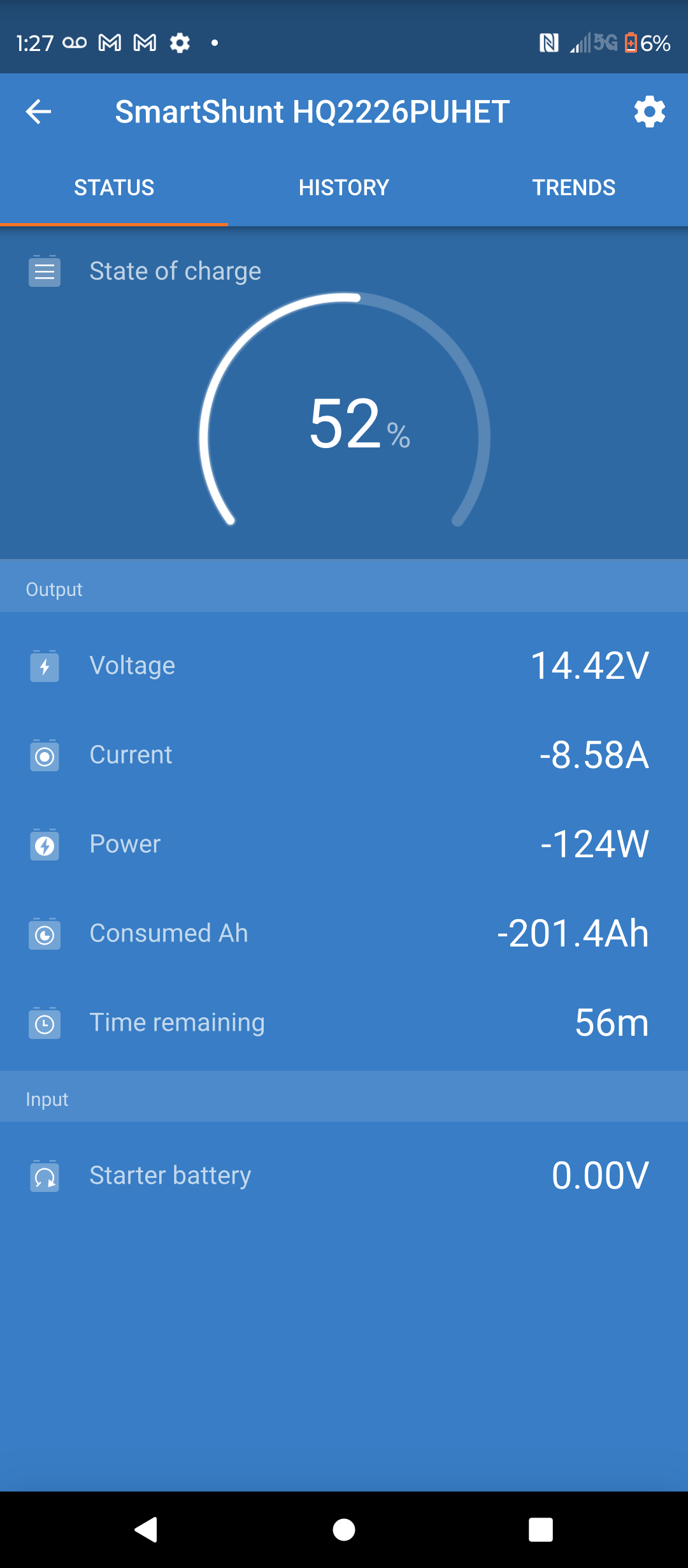
 I have Synchronized SOC to 100% on a couple of occasions when the Voltage shown from the Smart Shunt was more than 14V. After each synchronization, the SOC shown has been dropping based on Watt Hours drawn from the battery, but the Smart Shunt does not seem to be recognizing that power is being put back into the battery from my solar panels. I took the attached screenshots a couple of days ago when it became obvious the SOC from the Smart Shunt was incorrect. The SOC from the Smart Shunt has continued to drop since to the point where it now shows 0%, even though the Voltage shown is always above 13V and under mid-day sun, it always goes above 14V. What am I doing wrong?
asked
State of Charge Value Showing for my LiFePO4 Battery is Not Correct
What are your charged voltages on mppt?
Second, asking since this is a common error, is everything negative attached to the shunt and nothing between the shunt and the battery?
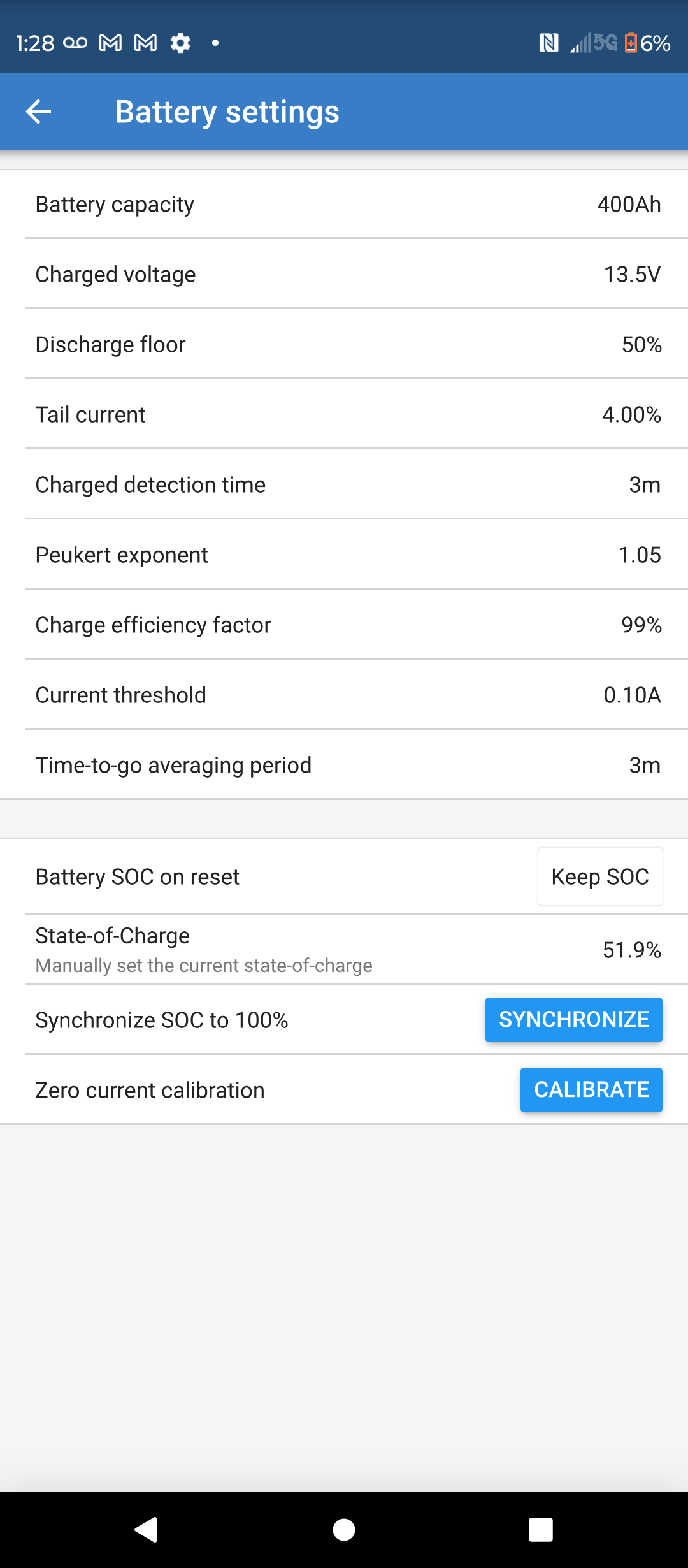
SOC is fairly close to correct reason I am saying this is 400Ah - 201.4Ah is just under 50%. So it is probably related to peukerts. Maybe try 1.03 instead.
Thanks for responding, Alexandra. My charge controller is a Renogy Rover 40 Amp MPPT and the battery type is set to Lithium, so I believe it should be going to Float mode after it measures about 13.5V on the battery. At the time I took the screen shot, my charge controller and inverter were both showing about the same voltage as the shunt, around 14.4V. I have 2 new Li Time batteries of 200 Ah each, connected in parallel. One side of the shunt is connected to the negative terminal of one of the batteries with the other side connected to the inverter.
I will try setting the Peukert Exponent to 1.03 and report the results back here.
As @Alexandra asked before, is anything, except the shunt battery side, connected to the battery negatives?
The renogy should be connected to the side of the shunt where the inverter is.
Sorry, I guess I didn't understand this comment on first reading. You are saying the charge controller's negative terminal should be connected to the negative terminal on the inverter, correct? I want to be sure before I change something that ends up damaging my equipment.
Thanks for your input, kevgermany, and Alexandra. The charge controller positive terminal is attached to the positive post on one of the batteries. The charge controller negative terminal is attached to the negative post of the other battery. That second battery's negative post is also attached to the battery end of the shunt. The other end of the shunt is attached to the negative terminal of the inverter. One of the thin red wires that came with the shunt is connected to the pin labelled E in the manual's diagram, with the ring terminal end attached to the first battery's positive post. (I did not do anything with the other red wire. It is still in the box.) The positive terminal of the inverter is attached to a fuse, the other end of which is attached to the positive post of the first battery. Except for a breaker between my 800 Watt solar panels and the charge controller, and more fuses between the solar panels and the breaker, that is my entire system.
Today, after 3 or 4 hours of direct sunlight, the shunt is showing SOC of 81% and battery voltage of 14.52, so I don't think changing the Peukert Component did anything. (For what it's worth, the Renogy charge controller is showing SOC of 100%). When I changed the Peukert setting yesterday afternoon, the voltage was showing as 14+ and the SOC remained at 0%, so I synched the SOC up to 100%. A couple of hours later, the shunt SOC was showing as 97%.
Now I'm wondering if I missed something in setting up the shunt. I did not connect the 2nd red wire because I assumed the shunt would see my parallel-connected Li Time batteries as one battery. Should that 2nd wire be attached to the positive post of my second battery (the same battery to which the shunt is already connected)? My reading of the manual led me to believe that second wire had been included for auxiliary purposes.
You wrote "The charge controller negative terminal is attached to the negative post of the other battery."
this is wrong, as the charge controller negative is connected to the battery the shunt can not measure the charge current.
The charge controller negative must be connected to the shunt on the same terminal as the inverter so charge current goes through the shunt.
The only thing connected to the battery side of the shunt is the battery and the only thing connected to the battery negative is the shunt.
Thanks, pwfarnell, after reading Alexandra's 2nd comment, I came to understand what you are saying. I have now connected the negative terminal of the charge controller to the inverter, instead of the battery. Hopefully, that will do the trick. If it doesn't, I'll come back here, but I am confident the problem is now solved.