question

electronicsuk avatar image
electronicsuk asked

EasySolar II GX "External current sensor connected" bug

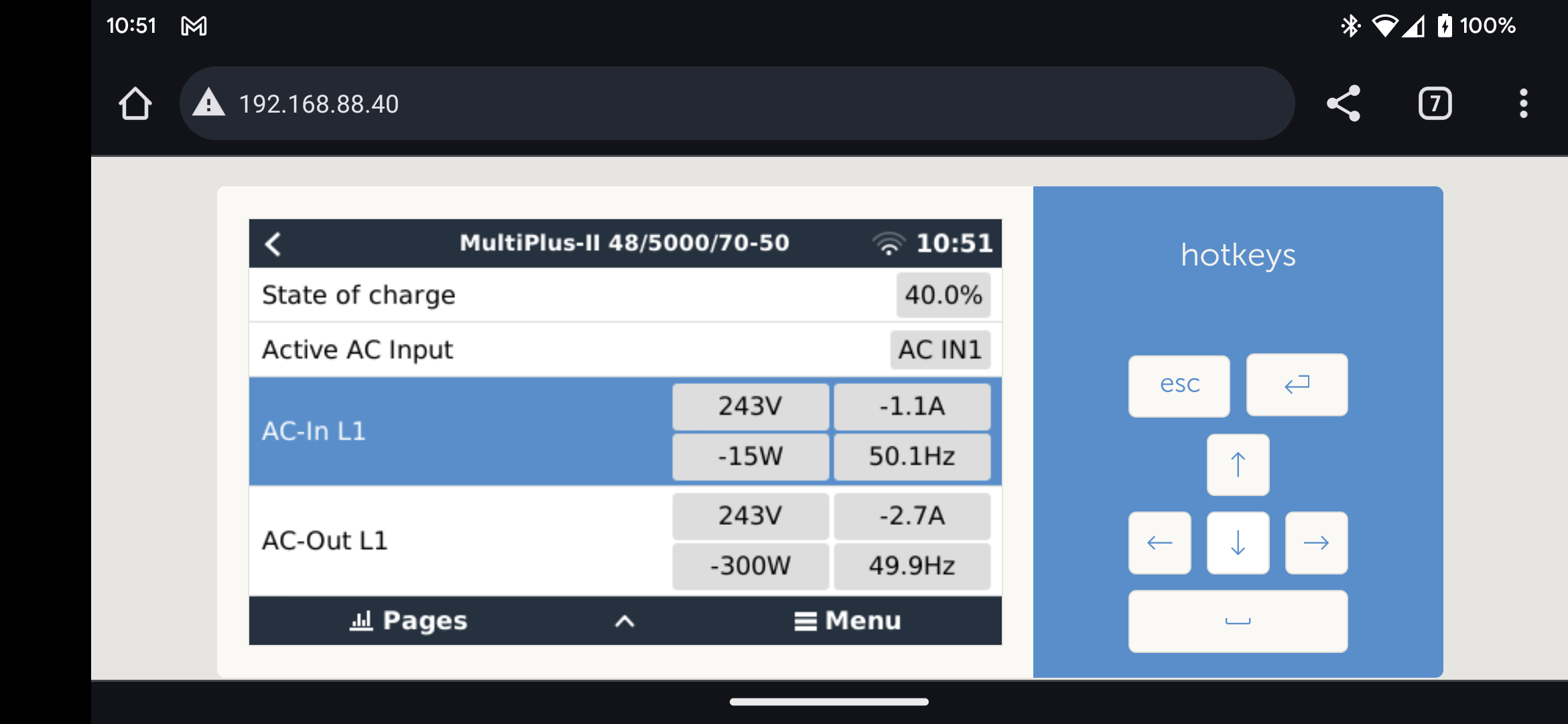
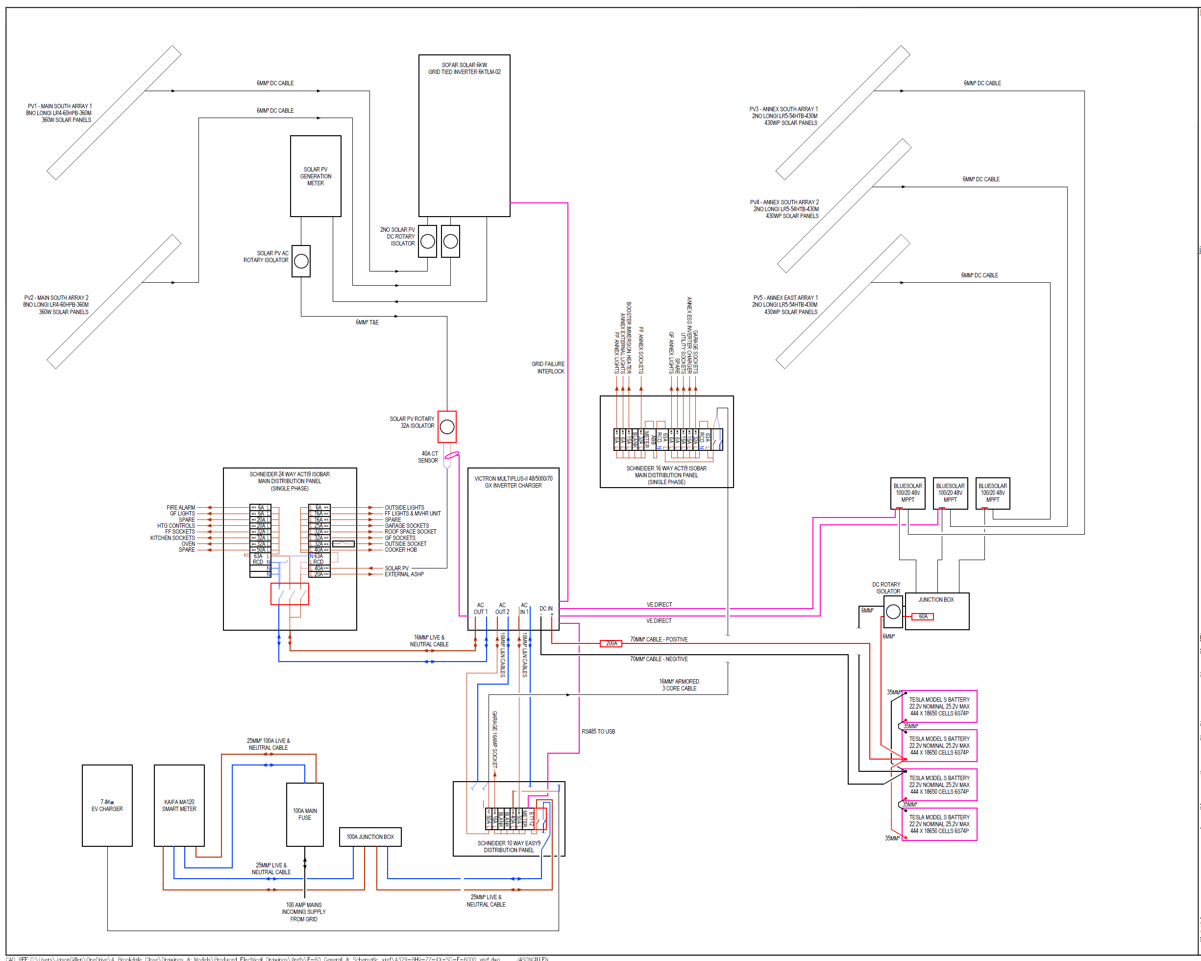
EasySolar II GX with the Victron 100A:50mA CT connected as the grid sensor. Regardless of "External current sensor connected" being checked in VEConf, the inverter treats the CT as if it were internal.

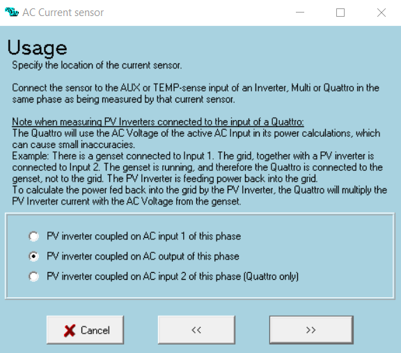
By that I mean, if AC PV is connected to AC Input 1 (between the CT and the inverter), and a 40A current sensor assistant is configured for the AC PV, the grid power is calculated incorrectly. It seems that grid power on the dashboard = grid CT + PV CT, which means the PV power is measured twice, as it already goes through the grid CT. The inverter is still treating the grid CT as if it were inside the inverter, even when fitted externally.

I've confirmed this behaviour with an owner of another system, it isn't an isolated case. When the external CT is fitted, it should be treated the same way as an external energy meter and wired as per Victron's own guide here:

https://www.victronenergy.com/live/_detail/ess:ess_with_multiplus-ii.png?id=ess%3Aquick-installation-guide


bug report
2 |3000

Up to 8 attachments (including images) can be used with a maximum of 190.8 MiB each and 286.6 MiB total.

7 Answers
electronicsuk avatar image
electronicsuk answered ·

Any way to get this seen by Victron? I've already reported to my dealer, they can't see anything wrong with my config and their only recommendation was to post on here. I've even managed to dig up a training presentation that shows exactly my configuration of multi with external CT and PV wired between the CT and Multi, so I'm confident it's not an issue with anything I've done.

2 |3000

Up to 8 attachments (including images) can be used with a maximum of 190.8 MiB each and 286.6 MiB total.

Jason - UK avatar image
Jason - UK answered ·

@electronicsukDo you have anything connected to the AUX1 connection on your unit?

Also, just checking you do have the sensor fitted the correct way round, noting the arrow on the sensor is the direction of import?

I think you have to set the 40A PV CT sensor as on the AC-OUT of the multiplus, as much as the PV is connected to the AC-In of the MP, the MP doesnt defenchate between grid-side laods and loads on the outlet side of the MP. If you make this change, it will show your PC on the AC-Out side but you will get the correct calcualtion.

If you want the PV to be shown on the AC-In side of the MP, you will need to use a ET112 meter or simular.

1703237928916.png


1703237928916.png (85.9 KiB)
2 comments
2 |3000

Up to 8 attachments (including images) can be used with a maximum of 190.8 MiB each and 286.6 MiB total.

electronicsuk avatar image electronicsuk commented ·

Hi Jason. No, nothing on AUX1. The PV CT is connected to TEMP IN. The grid CT is connected correctly and the right way around, confirmed both by arrow on the CT and it does read correctly apart from when the AC PV is running.

As you say, ET112 is a "solution" but according to Victron's own training notes, the CT is a perfectly acceptable configuration even with grid connected PV, so this is something that ought to be sorted in the software.

I actually already tried telling VEConf that the AC PV sensor was on the AC output, which does correct the grid calculation, but then it just messes up the AC loads calculation instead.

To be honest, everything seems a bit "off" when using the multi with an external CT. For example, I'd expect to be able to see critical loads on the AC out separately on the dashboard, but that doesn't work either. As I understand it, the multi has a separate CT internally for combined loading of AC outputs 1 and 2. Again, this is something that the software really ought to correct for when the external current sensor option is checked. I suspect it's all related.


EDIT: Yes, I'm in the UK.

1 Like 1 ·
Jason - UK avatar image Jason - UK electronicsuk commented ·

@electronicsuk In short, by fitting a external CT sensor, all you are doing is moving the location of where the MP is measuring the current on the AC-In. It is not the same as having a grid meter. By fititng the external CT sensor, which therefore disconnects the internal CT sensor, there is no means of seperating the 'critial loads' and the 'grid loads'. Therefore if you set your 40A PV CT sensor on the AC-IN, the MP thinks it is before the 100A CT sensor. Because of this, you need to set the 40A as fitting on the AC-Out of the MP.


This obiouslly shows the PV on the AC-Out side of the MP in VRM. The only way to show the PV on the AC-IN is to have a proper grid meter like the ET112. With a ET112 fitted, the MP then calculates the difference between the ET112 and the CT sensor, and shows that as grid loads. Everyhting else is then shown as critial loads. If your PV is fitted to the AC-IN, it will be displaied in VRM as on the AC-IN side of the MP in VRM.

People oftern confuse the external CT sensor as provding the same function as a grid meter, just like I did when I first got involved in Victron products.

2 Likes 2 ·
kevgermany avatar image
kevgermany answered ·
2 |3000

Up to 8 attachments (including images) can be used with a maximum of 190.8 MiB each and 286.6 MiB total.

electronicsuk avatar image
electronicsuk answered ·

Hi Jason. I tried to reply but for some reason my post got stuck waiting for moderation, still no sign of it so I'm trying again. I can give you a call but for the benefit of anyone else with the same problem in future, if might be better to stick to the forum? I know from personal experience how frustrating it is to find someone else with the same problem as you but no clear answer!

I'm still a bit confused why the external CT isn't treated the same as a grid meter. Let me explain why:

  • The CT is obviously directional, so the multi knows what's going to and from the grid.
  • As I understand it, the multi contains two CTs. One on the AC in and one combined for the two AC outs.
  • Fitting the external CT disconnects the internal AC in sensor, essentially replacing it.

If all those assumptions are correct, then:

  • Regardless of whether you have additional loads or generators on the AC Input, the multi still knows exactly how much is going to and from the grid.
  • The only reason to have a separate CT for the AC PV is to be able to monitor solar production. The multi should still be able to maintain grid setpoint in ESS, because it will see the PV as export and either charge the batteries or reduce its own output.
  • The multi has to simply not include the AC PV current sensor in the grid calculation in the dashboard. This is proven by removing the AC current sensor assistant and running the AC PV. The grid power then displays correctly. Grid power reduces and eventually starts to export or charge the batteries as PV inverter output increases. The multi still respects the grid setpoint, as one would expect, as the AC PV is being metered by the grid CT.

So, the AC PV CT should be purely for display purposes and calculation of solar yield whenever the external CT option is checked. There's no reason to arithmetically add it to the grid CT reading, it's already included as all loads and generators must pass through the grid CT to get to/from the grid.

I can perhaps understand why critical loads can't be displayed separately if the CT on the AC output is upstream of the relay that connects input to output, as the multi might be using it to regulate its output power. I can't understand why this should make any difference to how the grid power is calculated in relation to the AC PV.

Maybe someone from Victron can share a slightly more detailed block diagram of how the multi's internal CTs are positioned in relation to the inputs, outputs and relays?

2 |3000

Up to 8 attachments (including images) can be used with a maximum of 190.8 MiB each and 286.6 MiB total.

electronicsuk avatar image
electronicsuk answered ·


Perhaps this is a better example, as I actually have a bit of solar output today to demonstrate. Here's what the dashboard is reporting:

1000011105.png

And here's the multi:

1000011104.png


The multi's AC in is measuring the true grid power, which is close to the 0W grid setpoint. The AC PV is generating. Firstly it feeds the loads, any excess beyond that is going to battery. Obviously I don't really have zero AC loads, but that's how it's being reported when the PV is running.

With external current sensor option checked and AC current sensor assistant configured on AC in, what should be happening in the dashboard is:

  • The Multi's AC in should be reported as the grid power
  • AC loads should be reported as [grid power] + [AC PV] - [battery power]

For example, if we were exporting 500W, generating 1000W AC PV and putting 100W into the battery:

AC loads = -500 + 1000 - 100 = 400W

All the information is there to be able to do this.


1000011104.png (170.7 KiB)
1000011105.png (193.4 KiB)
2 |3000

Up to 8 attachments (including images) can be used with a maximum of 190.8 MiB each and 286.6 MiB total.

Jason - UK avatar image
Jason - UK answered ·

@electronicsuk

  • 'As I understand it, the multi contains two CTs. One on the AC in and one combined for the two AC outs.'
    Incorrect. There is only one CT sensor, on the AC-IN. The information provided as 'AC Loads' is the difference between the AC-IN CT sensor and the inverter/charger. Becuase of this, if you use the external CT sensor, the point of AC-IN measurement is extended to include any loads between the external CT sensor and the inverter charger. Any PV input by defult is shown after the MPII becuase it has now way of calculating it location.

Edit:

On this basis, if you have no grid meter, and are using a CT sesnor on let say your incoming mains cable tails, the multiplus has no way of calculating the differance between loads before the MPII and after.

If you use my schematic as an example, if I removed the ET112, and replaced it with a external CT sensor (as I used to have before), the MPII can only calculate

External CT sensor +/- inverter / charger = AC Loads

PV CT sensor = PV Inverter generation

1703332665901.png


Because I now have a ET112 grid meter, the MPII can calculate the difference between

Grid meter - Internal CT sensor = grid loads
Internal CT sensor +/- inverter charger = Critical Loads
PV CT sensor = PV Inverter generation

https://vrm.victronenergy.com/installation/171934/share/db6807bb


1703332665901.png (310.3 KiB)
2 |3000

Up to 8 attachments (including images) can be used with a maximum of 190.8 MiB each and 286.6 MiB total.

electronicsuk avatar image
electronicsuk answered ·

Thanks Jason, that all makes a lot more sense now and explains perfectly why critical loads can't be displayed separately without an energy meter.

I stand by my original statement that there's a bug in the grid load calculation with AC current sensor assistant on AC in. The system does have all the information it needs to correctly display the AC PV:

  • It's been told that the grid CT is external, by the setting in VEConf
  • It's been told, via the AC current sensor assistant setup, that the AC PV is connected on AC in
  • From the above, it can be inferred that the AC PV is tied in between the grid CT and AC in 1, and in fact that's exactly how it's shown in the Victron training notes
  • It knows the power output of the AC PV thanks to the 40A CT
1 comment
2 |3000

Up to 8 attachments (including images) can be used with a maximum of 190.8 MiB each and 286.6 MiB total.

Jason - UK avatar image Jason - UK commented ·

@electronicsuk I don't disagree with you on that one, that was my original interpretation when I first set up my system. I wouldn't say its a bug, just a limitation of the options available in control because all it is, is a different way of calculating the data. AC-In is still anything before the CT sensor, internal or external.

One other point to note, a external CT sensor is not truly accurate, even more so during low loads but has next to no latency whereas the grid meters are near 100% accurate but have notable latency. Given the number of calculations the GX device has to do and the need for one part of the calculation to be accurate, I wonder if that's the reason Victron limit the off the shelf options to what we have access to, so not to overload the GX device with calculations whilst also trying to control the connected items 100 times a second. I'm sure there is a means of using Node Red to provide what you mention above, PV on AC IN whilst using a external CT sensor but I myself have never explored that within Node Red yet.

1 Like 1 ·

Related Resources

Additional resources still need to be added for this topic