question

whiston-marine-services avatar image
whiston-marine-services asked

BMV 702 installation

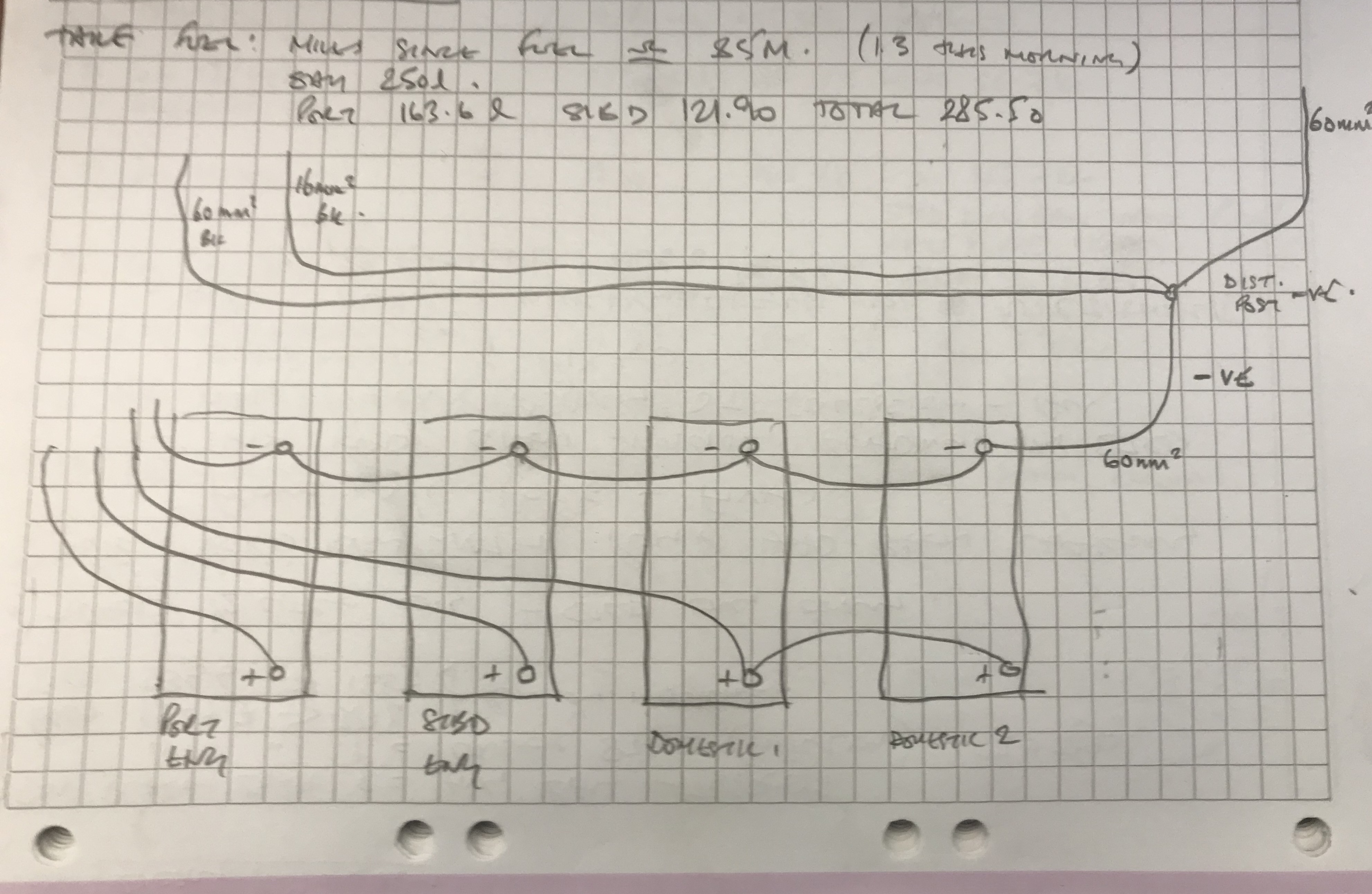
Here is my boat’s batteries layout, I’ve connected the shunt to the 16mm earth wire coming from the common stud, which then feeds the auxiliary circuits. I don’t seem to be getting any figures for discharge & the state of charge seems to always be 100% with time-to-go at infinity, any comments please

installation
2 |3000

Up to 8 attachments (including images) can be used with a maximum of 190.8 MiB each and 286.6 MiB total.

5 Answers
whiston-marine-services avatar image
whiston-marine-services answered ·

All sorted now, BMV 702 appears to be working as it should after I rewired the shunt.

It was actually just a case of RTFI.

Thanks for your input.

2 |3000

Up to 8 attachments (including images) can be used with a maximum of 190.8 MiB each and 286.6 MiB total.

Guy Stewart (Victron Community Manager) avatar image
Guy Stewart (Victron Community Manager) answered ·

Hi @Whiston Marine Services,

I am confused by your diagram. There are wires leading off the page that don't seem to be connected to anything?

Please have a look at both the "Wiring Unlimited" book here about wiring multiple batteries together - https://community.victronenergy.com/questions/10063/wiring-unlimited-a-new-book.html

And then the BMV wiring diagram here:

https://community.victronenergy.com/storage/attachments/833-1547720488224.png


2 |3000

Up to 8 attachments (including images) can be used with a maximum of 190.8 MiB each and 286.6 MiB total.

kai avatar image
kai answered ·

The shunt needs to be cut into the return path so it picks up the sum of all currents. Like Guy I'm not 100% sure of how to read the diagram. My best guess is the shunt should be placed between "-ve distribution post" and the -ve terminal on domestic batt #2. This will then read the sum of currents drawn from/pushed into the 4 batteries.

Just out of interest what caused a need to have port and stbd batteries rather than grouping everything together?

edit: re-reading your question, are you trying to measure the total current for all the 4 batteries or the current for a specific set of auxiliary circuits?

2 |3000

Up to 8 attachments (including images) can be used with a maximum of 190.8 MiB each and 286.6 MiB total.

whiston-marine-services avatar image
whiston-marine-services answered ·

I’m away from the boat just now, so can’t further investigate the actual battery wiring setup until I’m back onboard.

To answer @kai the Port & starboard batteries are engine starter batteries only, I assume they are kept separate so that if one battery developed a fault, it would not pull the other battery down, therefore it would always be possible to start one engine or the other, then throw the coupler switch & start the other.

The object of the BMV 702 is to monitor the domestic bank (of 2 x 95A batteries) and also show the voltage (only) of 1 of the starter batteries, I have wired B2 from the shunt to the Port battery, therefore I am only monitoring the voltage of that battery.

I will try, when I’m back, wiring the shunt between the negative terminal of domestic battery 2 and the negative distribution post and hopefully then the BMV 702 will be fully functional

2 comments
2 |3000

Up to 8 attachments (including images) can be used with a maximum of 190.8 MiB each and 286.6 MiB total.

kai avatar image kai ♦ commented ·

I would suggest then ensuring the shunt only read return current for the domestic bank (rather than domestic + starter batteries):

The negatives of the port & stbd batteries should go direct to the -ve distribution post and are not wired directly to the -ve of the domestic bank. This means that the return path for the starter batteries bypass the shunt (as per your objective).

This should make the BMV happy. If you have to rewire the port/stbd battery negatives, please check that the rewiring doesn't break something else.

0 Likes 0 ·
whiston-marine-services avatar image whiston-marine-services kai ♦ commented ·

Definitely sounds like a plan. I’ll look into this properly when I’m back.

I do get the logic regarding splitting the wiring of the starter battery negatives away from the auxiliaries, so I’ll do a little more investigation and give that a go.

Nice one.

0 Likes 0 ·
whiston-marine-services avatar image
whiston-marine-services answered ·

Hi @Guy Stewart (Victron Community Manager)

The wires leading off the page are:

Port engine battery positive - to Port engine starter

Stbd engine battery positive - to stbd engine starter

Positive from linked domestic batteries - to feed domestic circuits only (assumed)

Negative from domestic battery 2 - to negative distribution post

Negative from Port engine starter battery - to be confirmed??

2 x 60mm2 black cables from negative distribution post - assumed one each to each engine

1 x 16mm2 black cable from negative distribution post - assumed feeds domestic circuit??

2 |3000

Up to 8 attachments (including images) can be used with a maximum of 190.8 MiB each and 286.6 MiB total.

Related Resources

Additional resources still need to be added for this topic