Hello,
I have some questions about wire and fuse calculations. I've done some work, but would like some additional advice ...
My setup:
3x Multiplus II 5kVA (+ space for 3 more in the future),
1x MPPT RS 450/200 (+ space for 1 more in the future) with 4 strings of 9 x 410Wp panels,
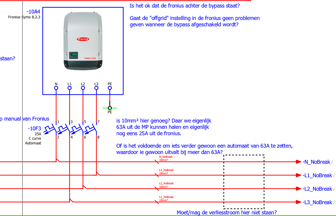
1x Fronius symo 8.2.3 with 1 string of 12 x 410Wp panels,
3x Seplos 16S 280Ah battery pack.
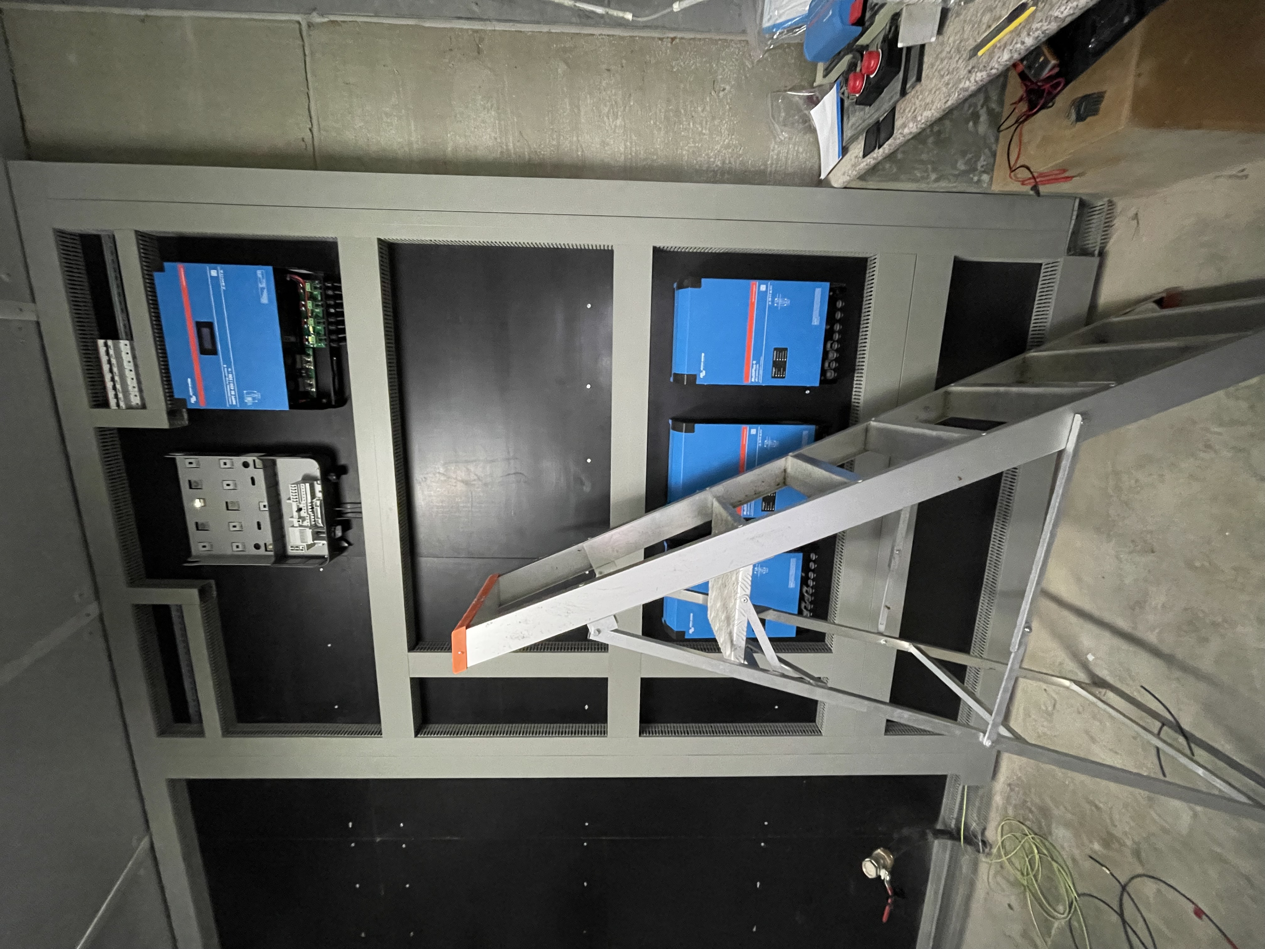
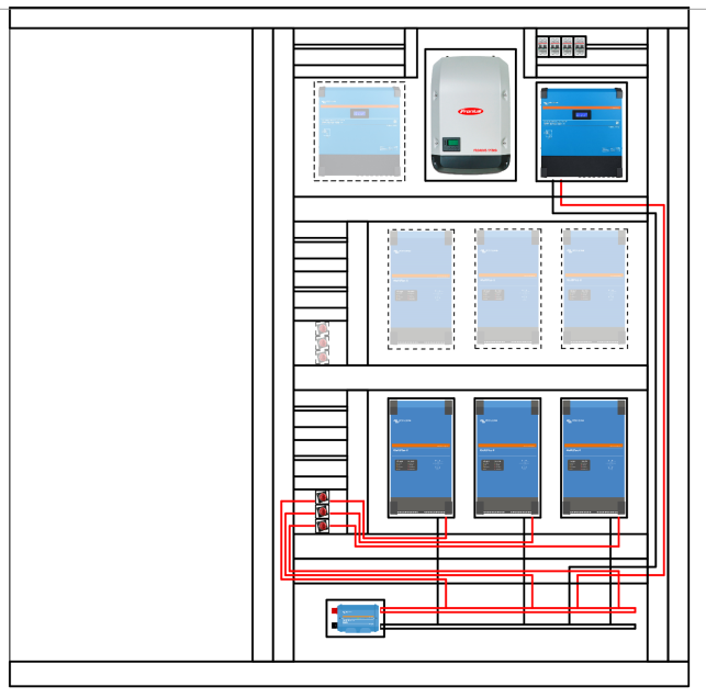
Just for info the progress up to now:
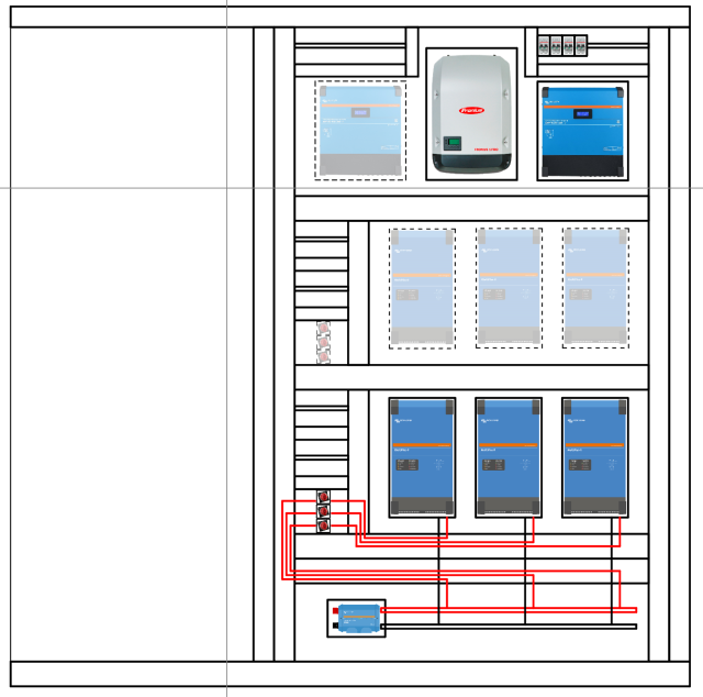
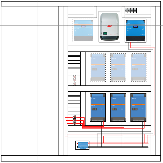
The electrical drawing as i am for now:
Some questions:
Q1:
As I read it's important to keep the lenght of the DC cables equal. What i read was:
Lenght of the DC cables from Multiplus to Lynx have to be the same.
Do they mean the circuit cable lenght must be the same, or each individual cable has to be the same. So is it:
[(lenght cable MP1 + to lynx) + (lenght cable MP1 - to lynx)] = [(lenght cable MP2 + to lynx) + (lenght cable MP2 - to lynx)] = [(lenght cable MP3 + to lynx) + (lenght cable MP3 - to lynx)]
or
(lenght cable MP1 + to lynx) = (lenght cable MP1 - to lynx) = (lenght cable MP2 + to lynx) = (lenght cable MP2 - to lynx) = (lenght cable MP3 + to lynx) = (lenght cable MP3 - to lynx)
I ask because if the second one is the only good solution, this couldn't be ok:
Q2:
An other thing i read was that the cables from MP to Lynx have to be the same lenght as the lenght of the cables from MPPT RS to Lynx. Is that necessary? My total lenght of cable from MP to Lynx is +- 4,5m, while the cable from mppt RS to Lynx is +- 9m.
IF the cable lenght has to be the same, i guess the real meaning is: the resistance of the cable has to be the same. So in stead of making the cable from MP to Lynx 2 times larger (which wouldn't be the best idea), i could make the cable twice as large. So if the cable of the MP to Lynx would be 70mm², I could make the cables of the MPPT RS to Lynx 2x 70mm². Which would work, because i have 2 x2 connections on the MPPT RS.
That being said, i did the calcution for the resistance of + cable from MP to Lynx:
(6x 0.06mOhm + 4,5m*0,27mOhm/m + Rswitch?? --> 0.1mOhm) = 1,675mOhm
and the calculation for the resisance of the + cables from MPPT RS to Lynx:
(4x 0,06mOhm + 9m * 0.27mOhm/m) voor 1 kabel = 2,59mOhm, voor 2 kabels in parallel: 1,295mOhm.
Thats a significant difference. How correct/crazy do i have to be for this?
Q3:
connection of the MPPT RS to the lynx:
What is the better connection knowing i have an other mppt RS that could possibly be used in the future:
option 1:
option 2:
Or an other option...???
Q4:
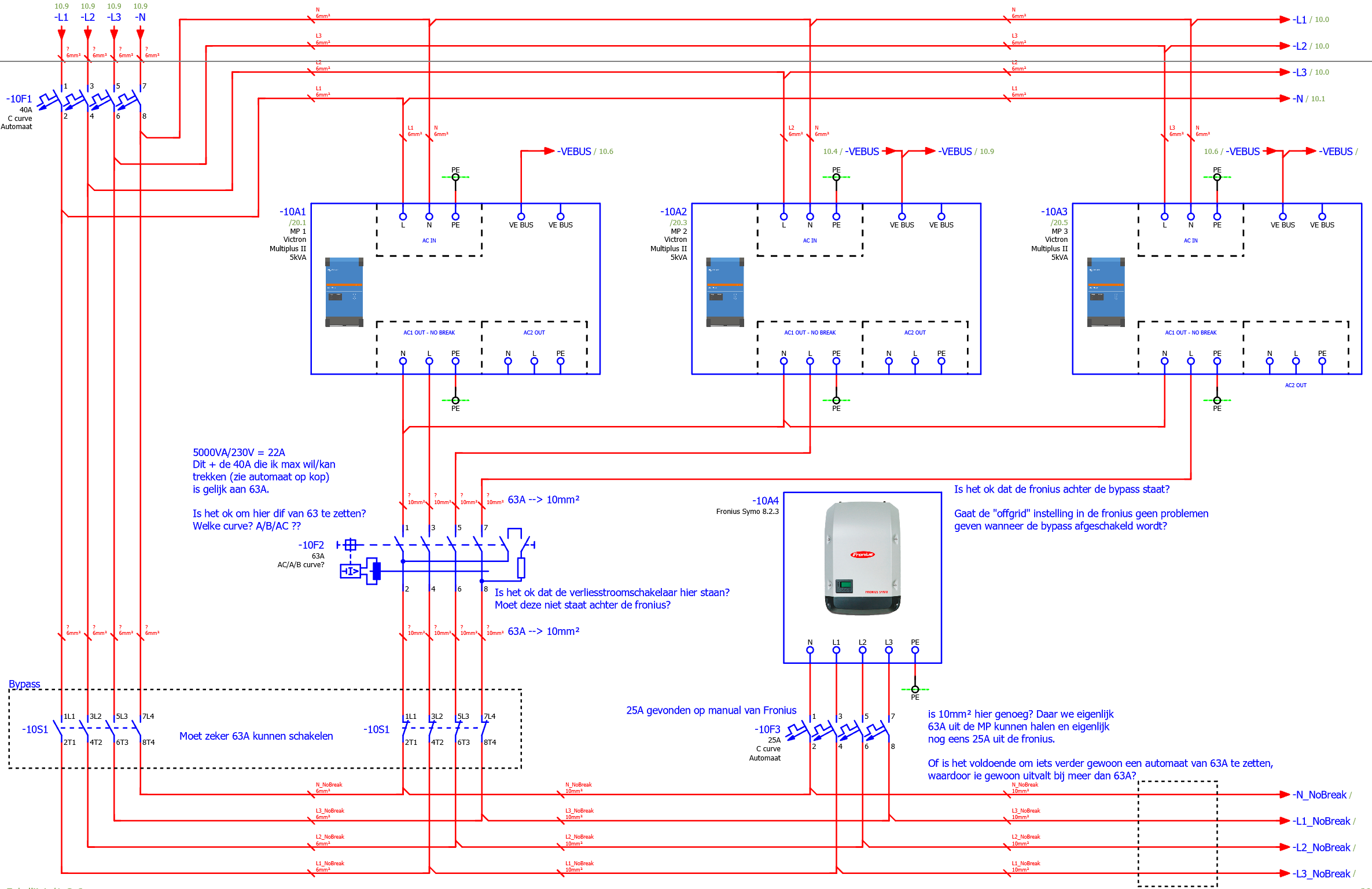 Please check out 10F1. I saw drawings where this was a C type and others where it was a D type. Which one does it need to be please?
Q5:
Again 10F1. I saw drawings where 10F1 was one 3 fase breaker and other were it where 3 monofase breakers. Which one is better?
Q6:
10F2 is a differential breaker after the no break. i made it 63A. The reasoning: 5000VA/230V=22A that i can maximum get from the batteries + 40A that i can get maximum from the netside (because of 10F1). Together 62A, so 63 is the logical choice. Is this a correct assumption?
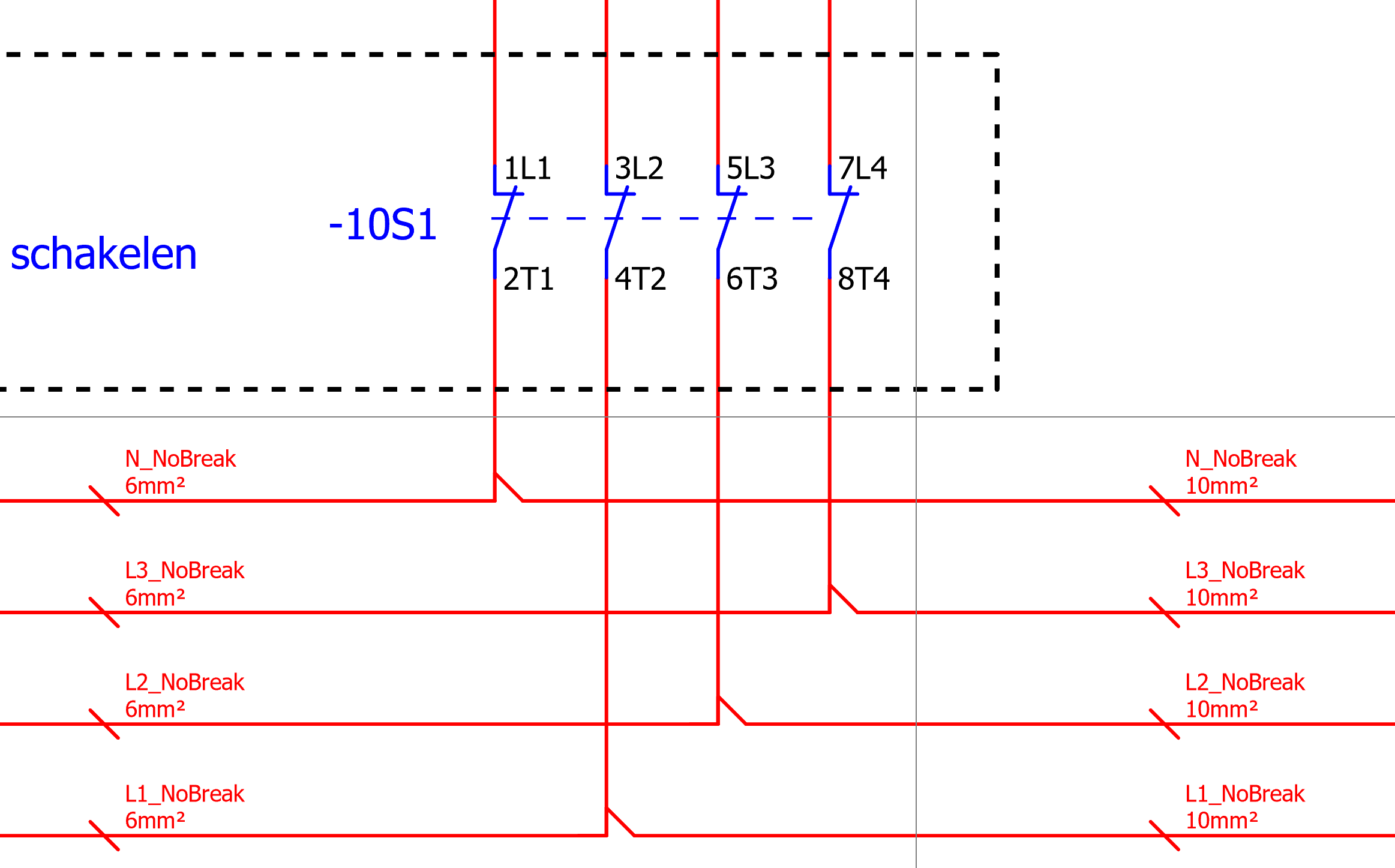
Q7:
10S1 is an bypass switch that can manually be switched when the system fails. Because i have 10F1 that has 40A, i limited the cable section directly through the bypass to 6mm². When the system works normally, is it correct to asses that there is no harm in connecting the 6mm² to the 10mm² wires after the no-break AC OUT1 from the MP's?
Q8:
10A4 is the fronius AC inverter. Is it correct to place it there, knowing that i want it after the MP's?
Specificly:
- I guess it does, but will it still work correctly when bypassing the MP's knowing the grid functions. Will the "microgrid" settings need to be reset for this to work?
- Is 10F2 in the wright place or does it need to be after the fronius? (in the place of the dotted rectangular)