question

kevin-cunningham avatar image
kevin-cunningham asked

Smoking DC-DC. Melted wires,

Victron Energy Orion-Tr Smart 12/12-Volt 30 amp

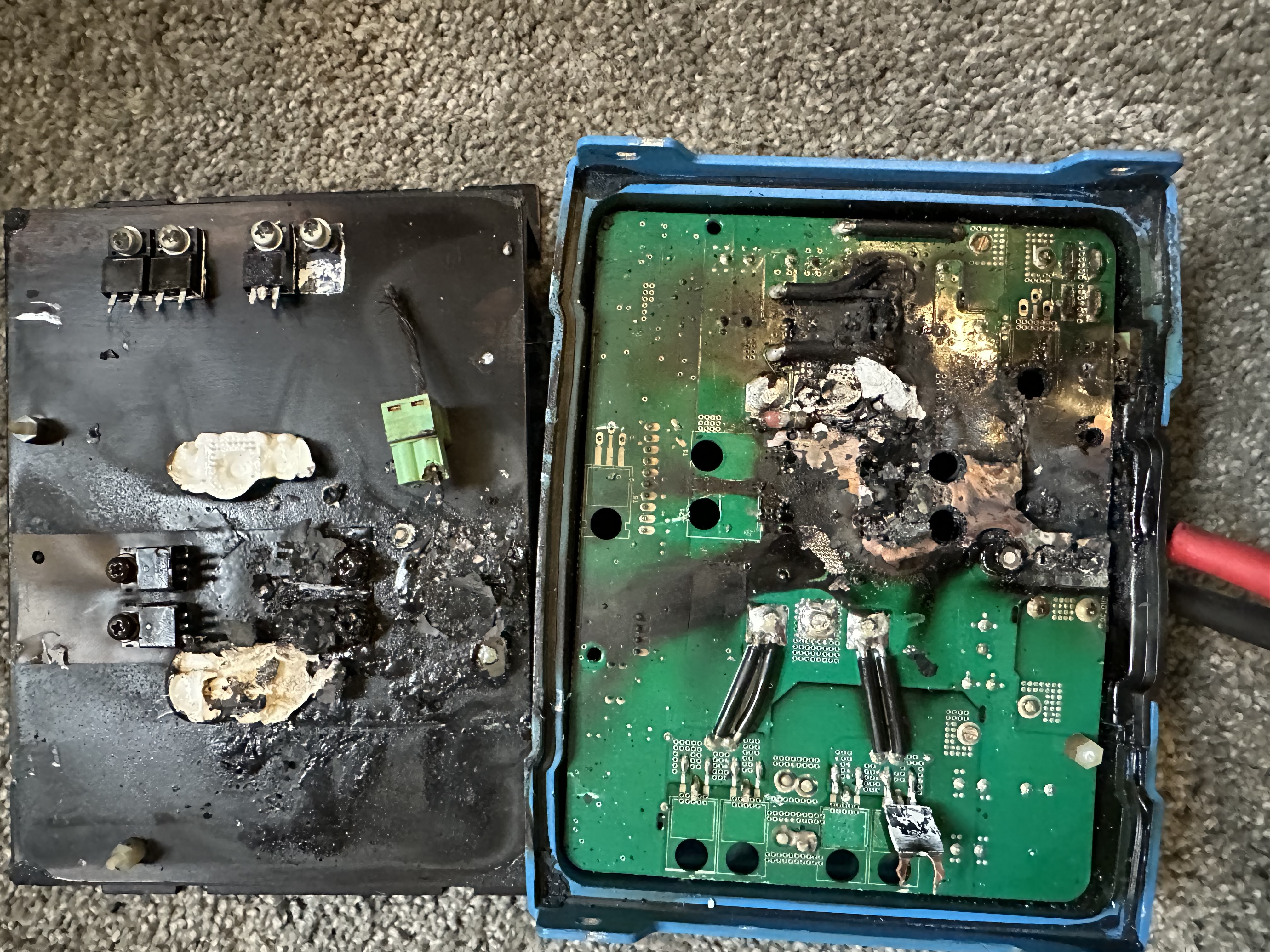
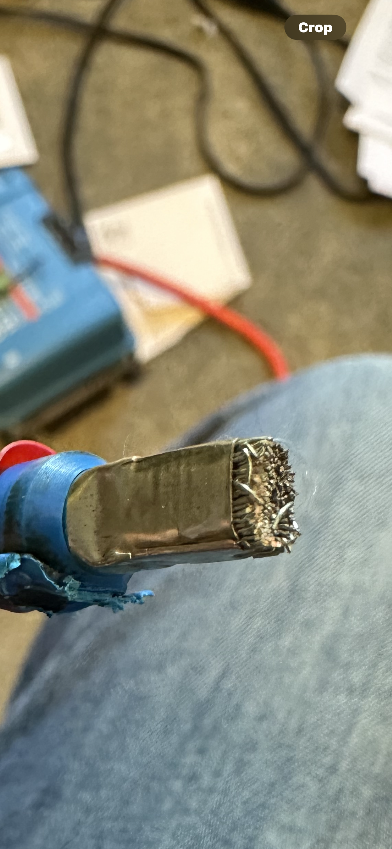
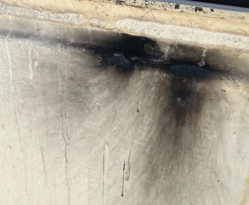
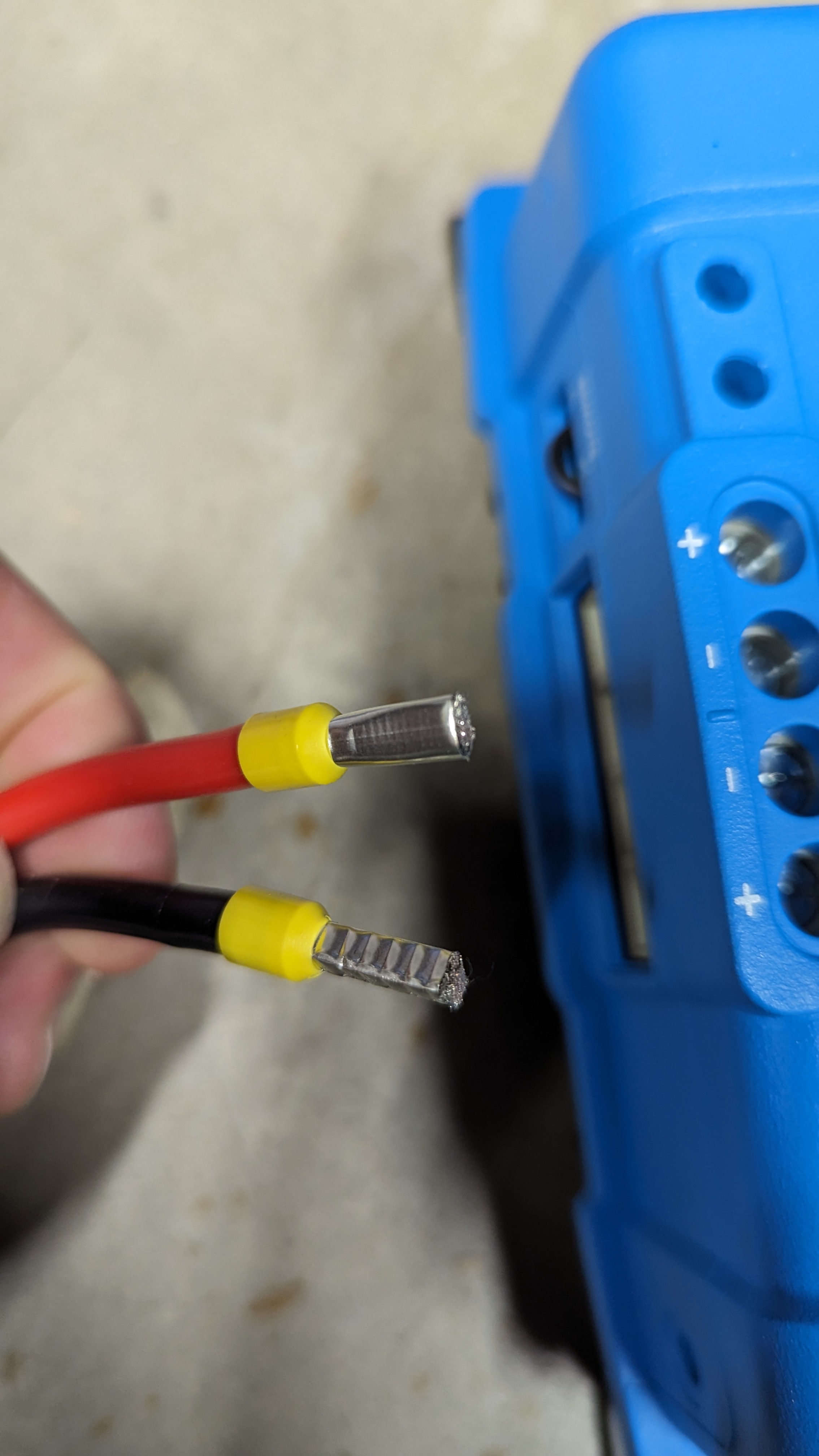
I have had the 12/12-Volt 30 amp installed on my boat since March of 2023. Worked well since install and the unit is installed in a well-ventilated area. Last week, started up the boat and after 90 seconds or so, the Engine instruments alarmed and then died, I then started smelling smoke. I opened the hatch where the Victron installed and thick arid smoke was coming from within the Victron. The 40A fuses on the input nor the 40A on the output was blown. The smoke and heat were bad, it was about to catch on fire. I tripped the breaker to the input and the smoke stopped shortly after. The unit is toast. The input (+ -) and remote switch wires are melted in place. Reached out for support, but really cant believe this happened.

Unit is connected to a Volvo D3 190 with a 140A alternator.

Unit is used to charge a 200 AH LifeP04 bank, that was at 100% when this happened.

Unit is fused with 40A breakers.

Orion DC-DC Converters not smart
2 |3000

Up to 8 attachments (including images) can be used with a maximum of 190.8 MiB each and 286.6 MiB total.

16 Answers
kevgermany avatar image
kevgermany answered ·

Sorry, but this is for your dealer.

2 |3000

Up to 8 attachments (including images) can be used with a maximum of 190.8 MiB each and 286.6 MiB total.

kevin-cunningham avatar image
kevin-cunningham answered ·

I was refunded, but no answer to why this happened. This was close to causing a fire and burning down the boat. img-0960.jpg


img-0960.jpg (3.6 MiB)
2 comments
2 |3000

Up to 8 attachments (including images) can be used with a maximum of 190.8 MiB each and 286.6 MiB total.

Craig Chamberlain avatar image Craig Chamberlain commented ·
Glad nobody was hurt and you prevented a fire. I would guess the most common cause of this type of thing is loose wires. Do you happen to know if the connections were properly torqued during installation and if they were subsequently checked? Also, probably worth testing your alternator before connecting it to anything else just in case either it caused the damage due to an internal regulator failure, or in case it was damaged in the incident.

I hope you find the cause whatever it might be.

2 Likes 2 ·
nesswill avatar image nesswill commented ·

To me this looks like the ground-plan has heated up probably due to a loose connection (high residences) on the negative connection. (as already suggested)

As said by others using the correct wire type and torqued to the recommended setting and regularly checked can avoided this type of problem.

It is unlikely to be a component issue as they usually just fail, crack or put a small dimple in the case.

Good luck and i hope everything else is ok.

0 Likes 0 ·
kevin-cunningham avatar image
kevin-cunningham answered ·

I would be happy to mail this to Victron to look into further.

2 |3000

Up to 8 attachments (including images) can be used with a maximum of 190.8 MiB each and 286.6 MiB total.

djsmiley avatar image
djsmiley answered ·

How were the wires connected? It looks like the source of 'ignition' might be the terminal (overtorqued or undertorqued), causing the connector to heatup. Since the device is mounted vertically, the fire did go in the upward direction, which matches the image which appears to have less damage on the top.
If the fets were the source, I would expect the PCB traces near the connector to be in better condition.
To me, it does look like a terminal/wiring failure tbh.

Did you torque the connector to spec?

1 comment
2 |3000

Up to 8 attachments (including images) can be used with a maximum of 190.8 MiB each and 286.6 MiB total.

Craig Chamberlain avatar image Craig Chamberlain commented ·
It would also be useful to see any photos before the unit was taken down. It's usually pretty clear where the initial source of heat was because that's where the damage is greatest. I would also like to see if the cables were mechanically supported with clips or if they were relying purely on the connector clamp. Lastly, what sort of wire was used? Was it fine strand or multicore and was it with or without ferrules? Multicore in particular is very prone to coming loose even if torqued to spec, due to the way the cores flatten out in the clamp.
0 Likes 0 ·
kevin-cunningham avatar image
kevin-cunningham answered ·

The breakers are blue seas 40A on the + input and + output legs. The house bank was at 100% as I just took it off the shore power. There was no load on the house at the time. This happened fast, just after starting the engines ( under 2 minutes), not enough time to overhead, there is also an ignition delay of 90 seconds, so this all happened right about the time the ignition delay was met.

The output + wire is the only thing that survived without a scratch. All wires are 6AWG marine wires. The input + and ground are both still connected to the Victron, the screws to clamp the wires are not visible enough to loosen to remove and cannot be pulled out.

Ferrules were used and crimped with head shrink. The connections to the unit were solid. torqued the connector to spec. It does not appear there was a loose connection.

Are there other possibilities than loose wire? Alternator, battery? The unit always got hot when in use, could that have contributed to an internal failure?

The unit was mounted vertically on a 12 x 12 x 1/8 Inch Aluminum Sheet Plate to help dissipate the heat, glad I did that and read on this forum the units get hot. Wires were secured in place, just below the unit. The unit was always hot to the touch when in use, I could not leave my hand on the unit for long.

The remote ignition switch was also connected and looks to have heat damage also.

Here is a pic of the output + crimp, the other wires cannot be removed.

Here is a pic of the hatch cover, which is about 5 inches above the Victron.


crimp2.pngsmoke.png


crimp2.png (6.7 MiB)
smoke.png (826.3 KiB)
2 comments
2 |3000

Up to 8 attachments (including images) can be used with a maximum of 190.8 MiB each and 286.6 MiB total.

kevgermany avatar image kevgermany ♦♦ commented ·
Just looking at the crimp, there's little sign of it being clamped. I usually tighten a lot more.
3 Likes 3 ·
Craig Chamberlain avatar image Craig Chamberlain kevgermany ♦♦ commented ·

I agree, it almost looks like the ferrule was crimped by the cage clamp alone without a ferrule crimp tool. When a ferrule crimp tool is used it usually leaves little indentations like in the attached image.

1699478776070.png

@kevin-cunningham can you confirm if a ferrule crimp tool was used or not?

2 Likes 2 ·
1699478776070.png (105.6 KiB)
kevin-cunningham avatar image
kevin-cunningham answered ·

The instructions listed the Torque as 1.6Nm and that was done. These wires were in there tight and could not be wiggled or moved at all and were fastened in place. Pre and post install, the wires are securely connected to the Victron.

To give your idea this was caused by a bad connection the benefit of the doubt, Wires were installed per specs, correct breakers, wire size, not corroded, not loose, could not be pulled out or wiggled. Ferrules were used and properly insulated. Pre and post install, the wires are security in place. Ground wire securely in place.

Yet this thing can still burn up to the point of a fire without any safeguards, fuses or heat related fail safes? I hope there is more to this than just that or this will be my last Victron.

Any other owners have one of these burn up? Why does the unit run at 45-56 Celsius when in use? Could the alternator be part of this?

https://www.victronenergy.com/media/pg/Orion-Tr_Smart_DC-DC_Charger_-_Isolated/en/installation.html

2 |3000

Up to 8 attachments (including images) can be used with a maximum of 190.8 MiB each and 286.6 MiB total.

Justin Cook avatar image
Justin Cook answered ·

This is unfortunately the result of a (visibly) poorly-crimped ferrule (from which I must assume the other two were similar) and loosening connections due to heat-cycling in the connector; heat cycling will occur in any case and as such all connections should be checked regularly in any installation, but of course when there is a poor crimp in the circuit that generates higher resistance and thus more heat and thus higher resistance etc, this heat cycling and its resultant effects are exacerbated.

It's good of the seller to issue a refund, though frankly a bit irresponsible since it's not a warranty issue and would have been an ideal opportunity to have a very serious discussion about the literal life-or-death critical importance of good connections in a DC system.

The fuses did not blow because it's not their job to blow in this instance - the fuses exist to protect the wire, and we can see that the wire is fine. There was no short-circuit, nor excessive heating of the wire; the heat is at the terminal connection, which can only arise due to poor contact -in this case, specifically poor contact at the DC input side- and is a clear case of a commendable attempt being made to install properly, but without the benefit of experience and seriousness to ensure that the proper methodology was used.

It's very fortunate that everyone is okay and no serious damage occurred, and I sincerely hope that this experience can be taken as a lesson going forward as well, to not only double-check everything else currently in the installation, but also to motivate and ensure more rigorous application of proper installation tools and techniques going forward.

2 |3000

Up to 8 attachments (including images) can be used with a maximum of 190.8 MiB each and 286.6 MiB total.

4pierre avatar image
4pierre answered ·

im adding an Orion to my system soon between my house batts and an auxiliary, so for science I tried with and without a crimp tool. Negative was crimped, and the ferrule is on tight. Positive I slid on there and torqued it to spec in the Orion then removed it. The ferrule could still be pulled off the hot wire after I removed it.pxl-20231109-040541592.jpg


1 comment
2 |3000

Up to 8 attachments (including images) can be used with a maximum of 190.8 MiB each and 286.6 MiB total.

4pierre avatar image 4pierre commented ·
and yes, I tossed it in the crimper after science was complete :)
2 Likes 2 ·
kevgermany avatar image
kevgermany answered ·

Something else on crimps. The correct size for the wire must be used. And the insulator is colour coded to show the size.

1 comment
2 |3000

Up to 8 attachments (including images) can be used with a maximum of 190.8 MiB each and 286.6 MiB total.

Craig Chamberlain avatar image Craig Chamberlain commented ·

Yeah, if the ferrule is sized and crimped correctly, it becomes part of the wire essentially. And those little indentations the crimp tool leaves will vastly increase the mechanical “grip” of the ferrule tube, making the wire very hard to pull out.

Personally though, in a good quality cage clamp, I would question the need for ferrules at all, but that is dependant on meticulous preparation of the stripped cable before insertion into the cage clamp. It should be easier to get a satisfactory connection using a ferrule but as you say here, it’s crucial to use the correct size ferrule tube and of course a good quality crimp tool.

Edit: Here is another community thread answered by @WKirby where a good explanation is given as to why ferrules are perhaps not required or desirable in this application.

https://community.victronenergy.com/questions/66259/orion-tr-smart-to-use-ferrules-for-16mm-wire-or-no.html

1 Like 1 ·
kevin-cunningham avatar image
kevin-cunningham answered ·

The unit worked for 120 hours this year (per engine hours) in this configuration and burned up in 30 seconds with no load on a cold morning. These are interesting and promising theories, over crimped, under crimped, not crimped enough, loose wires, loosening connections due to heat-cycling. These wires were and are tight, I still cannot remove or pull them out and I can see that they are still connected all the way through to the end of the ferrule.

I hope you are correct, yet if you are, then there are several design flaws that should be addressed, especially prior to being placed in a marine environment again. Even in a mobile environment would give me pause. Sounds like internal failure or bad rectifier is not a possibility.

Glad we have this forum to review this issue to supplement the Victron support and installation manual. If this forum and YouTube were not available, I might not have taken all the precautions for heat. I learned a lot even before I purchased.

Yes all were ok, Wife and son jumped on the dock while things were sorted out. One hour later, we would have been 25 miles offshore in 55 F degree water- so lucky for sure. If this did not spike and shut down the engine computer, I would not have known until this was too late. Thank you for asking !

The changes I would suggest-

  1. Proximity- separate the wire mounts so the +,- leads are not so close, with no physical separation.
  2. Heat- fix the heat issue. Way to hot, not enough cooling fins. Extreme caution noted when mounting, add a fan.
  3. The word heat does not appear in the installation manual.
  4. Add to installation manual, imperfect wire connection will lead to fire.
  5. Add 50 hour connection check on the Bluetooth app to remind every 50 hours.
  6. Add alarm when heat is above 55C or appropriate value.
  7. Add heat graph history to Bluetooth.
  8. Alert via Bluetooth for faults or alerts.
  9. Failsafe- if the unit is on fire, it should have a fuse the blows.
  10. Redesign how the wires mount. A nut and bolt mount is industry standard in marine environment.
  11. Other units do not have this heat issue- might be time to redesign.

Just some thoughts for designers of the DC to DC chargers.

4 comments
2 |3000

Up to 8 attachments (including images) can be used with a maximum of 190.8 MiB each and 286.6 MiB total.

Craig Chamberlain avatar image Craig Chamberlain commented ·

To be fair, I think there were a variety of theories until we saw the photo of the un-crimped ferrule but having seen that now, in my opinion this is absolutely the most likely cause. The 1.6NM torque is not enough to crimp the ferrule as well as secure the connection. You either need to omit the ferrule (my preference) or crimp it with an appropriately sized, square profile crimp tool and then torque to 1.6NM. In fact I would torque it and release it several times to ensure the ferrule has taken on the optimum shape of the clamp.

The reason I prefer NOT to use a ferrule with fine strand wire in this type of clamp is because this allows the wire strands to “flow” as the clamp closes until the strands completely fill the clamp aperture. For example, if your cable is 16mm2 and you insert it into a clamp that is 8mm wide, then the clamp can close right down to 2mm at which point the cable has spread to 8mm wide by 2mm high. That gives you 8+8+2+2 = 20mm (top+bottom+left+right) of contact all around the clamp. On the other hand if you crimp that same 16mm2 cable into a 4mm x 4mm ferrule, then unless the clamp torque is sufficient to flatten the ferrule down to 2mm thick, it will only be contacting the clamp at the top and bottom (4mm + 4mm = 8mm). If the strip length of the cable is say 10mm then without the ferrule you get 20*10 = 200mm2 of contact whereas with the ferrule you get just 80mm2. With an un-crimped ferrule, that surface area could be significantly less.

I also think this could have been the cause of excess heat generation because there would almost certainly have been a significant voltage drop across those connections which would have a corresponding power loss as heat. Maybe that excess heat then caused a component failure which would normally have caused a fuse to blow, but with a high resistance connection that fuse couldn't reach breaking point?

This is something that we test for in AC electrics where we ensure that the combined impedance of the line conductor and protective conductor (r1 + r2) is low enough to cause a high enough current to flow in the event of a fault, to trip the overcurrent protection device. In this situation you want around 5x the fuse current to flow, which in turn will trip the protection in under 0.4s. What you don't want is to have say 1.5x the fuse current flowing because that might take too long to trip the protection and things will get very hot in that time.

You mention that the wires were and are still tight but is it possible that they have just spot welded themselves due to arcing? This would produce a mechanically quite strong connection but it would be electrically very high resistance because the cross sectional area of contact would be very small.

I know, lots of theories and hard to know for sure what was the cause.

3 Likes 3 ·
beat avatar image beat Craig Chamberlain commented ·

Very interesting points @Craig Chamberlain !


Actually your contact area calculation will depend on the type of cage. Lately I had to check the wiring of an electrical AC high-amps Hager bypass switch (for bypassing Victron Multipluses during maintenance and upgrades). I couldn't measure any contact by measuring on the screws, nor on the metalic bottom of the cage clamp. Even the 2 sides were plastic. Wondering were the contact was, I discovered that only the top part of the cage was conducting. The metalic bottom part was not electrically linked to the upper part (at least in the unscrewed position) and empty of course.

For such cases, maybe square-crimped ferrules with professional (reputed-brand, DIN-certified) crimping tools bring a better connection, tighting firmly all 4 faces together and to the top of the cage, could be better than without ferrules.

Now, the Victron cages (at least of MPPT 100/20 and 150/35 seem to have metal all around, but then how well the moving part is linked with the main contact part will depend too of its internal construction. Given the relatively small torque, small screw size and "cheap" feeling of it, i'm not that sure that you can apply all 4 faces for the contact surface, best guess is only top and bottom (if well linked electrically in the clamp.

That said, e.g. for a MPPT 150/35 specified at 16 mm² clamps, you can't insert a square-"ferruled" thin-strands cable into it, only "unfferruled" 16 mm² ones, or "ferrulled" 10 mm² ones. And with only 1.6 Nm torque it's not a lot to make sure to have a great contact for many years, and that the screws won't unlock themselves, and more importantly, it's not enough to compress the cupper enough so that it doesn't have space around to flow/relax with time. To be on the safe side for a long period of time, my tiny but years-long experience shows that torques of at least 2.5 Nm are needed for 16 mm² and of at least around 2 Nm for 4-6 mm² wires, provided the cage specs allow it....

1 Like 1 ·
Craig Chamberlain avatar image Craig Chamberlain beat commented ·
Thanks for taking time to reply - I'm always looking to learn something new. :)

You're right, it does depend on the cage type but even if ONLY the top plate is 100% connected to the terminal, it's better to flatten the fine strand wire out to get say 80mm2 of CSA (8mm x 10mm strip length) than to have just 4mm * 10mm with an uncompressed square ferrule.

As for torque, firstly let's agree that wires should be mechanically supported and preventative maintenance should have us re-torque all connections on a regular basis. Assuming that is happening, I think the exact torque required to achieve sufficient clamping depends heavily on how flattened out the conductor becomes. Torque is converted by the thread into linear force applied to the clamp and this in turn applies a pressure which depends on the surface area of the conductor being clamped (P=F/A). I agree that 2.5NM would be better for 16mm2 though.

But something that was recently illustrated to me very clearly is that when strands are unable to "settle" or "flow" into position easily, it doesn't matter if you use 1.2NM, 1.6NM, 2NM or 2.5NM, if you just move that wire slightly it can just fall out! I witnessed this on my AC electrics where I had a 16mm2 multi-strand (not fine strand) cable into a cage clamp. I then torqued it up to the prescribed 2.5NM and shortly afterwards, while moving some neutral wires around the 16mm2 wire just fell out in front of me! I couldn't believe it! Then I realised that the slight movement was causing core settlement that was making the cable take up less space. The solution is to straighten out any twist in the cores and pre-flatten them with flat pliers before inserting into the clamp and torquing.

1 Like 1 ·
beat avatar image beat Craig Chamberlain commented ·

That's a very good tip! I learned something today! :-)

I had a similar experience on a multi-brain (gross strands - class 2) AC wire falling out with a big surprise despite a strong torque, and that's a very good tip to unwind them and slightly pre-flatten them. But then you need to make sure that each of the brains is in good contact and compressed when tightening the clamp too, especially if you are not putting them in a very strong cage with >3.2 Nm torque possible.

For fine strands - (class 5) DC cables, ferules start to really get flattened out to full width at around 2.5-2.8 Nm, As I understood it, the risk at those stronger torques without ferrules is that the fine strands get cut-off by the cage at the border ?

0 Likes 0 ·
beat avatar image
beat answered ·

These are good and constructive suggestions!

Although the free Victron Wiring book has them all inside and is a great read, even for professionals.

I can add to this list of ideas that my "emergency car charger" delievered with my 2015 Nissan Leaf electric car has a thermistor in its custom-made "standard" wall plug as an added security temperature probe, in case of a loose connections ... in the wall socket!

Thermistors are cheap and easy to integrate, and given the Victron market it could make sense to add such temperature probes near high amperage connections in the Victron units themselves. It could actually save money to Victron because of these returns, and avoid bad stories.

Even professionals make human errors, and most professionals don't have thermal cameras to detect loose crimpings (it's easy to make an error on the crimping tool setting, and a bit of extra heat is invisible).

I would add a few more suggestion for Victron @Guy Stewart (Victron Community Manager) to that list (different units, but obviously similar cable clamps:

- Use stronger clamping connectors (for the MPPT 100/20 at least), specified at 0.7 Nm ! Yes, zero point seven. Seriously ? did you try to screw at 0.7 Nm with a torque-meter ? The ferule isn't even compressed with 0.7 Nm. I had to up the torque to around 1.1-1.2 Nm (torque-measured) to get a firm connection (didn't want to go higher because of the tiny screws' specified max torque).

- The MPPT 150/35 has only 1.6 Nm (any serious electrical gear for high amperages has between 2.1 and 3.6 Nm torque spec). These are really small torques for such currents.

- Additionally the Wirebox M for MPPT 150/35's wire-clamp is too small for 16 mm² hallogen-free wires (actually wires are too near of each other, the small screw doesn't have the space between them). Even the Wirebox S's screw cuts a bit into the cable insulation, which is not good.

- For MPPT 150/35, it is specified for 16 mm², but a 16 mm² wire with ferrule doesn't fit in. Either 10 mm² with ferrule (but then distance must be short) or 16 mm² without ferrule are the maximum that can fit in.

- And write the specified torque onto the case, near the corresponding screw/bolt (Hager does that now finally for electrical gear, and solar inverter makers Fronius and Huawei do it too). I spend time writing and sticking stickers each time on Victron equipment, as finding the information in the manual each time (when screwing, when checking, and when inspecting) is time-consuming.

- Create a few new "products" "Victron professional DC wiring toolkit" with the right tools for given cable sizes, including cutting, crimping, torque-metered wrenches. Make the detailed list and sources available for people missing only one tool. Those tools-"products" could then be "rented" or resold by one-time installers.

1 comment
2 |3000

Up to 8 attachments (including images) can be used with a maximum of 190.8 MiB each and 286.6 MiB total.

Alexandra avatar image Alexandra ♦ commented ·
Since they are rising clamps, ferrules are not really in the design thought. The clamps allow for an install without them.


Ferrules don't allow the spread of the wires in the clamp correctly as well. So as convenient as they are for preventing flyaways etc, they are not the most correct thing for these terminals.

And as pointed out, terminal torque is affected which then affects heat that affects thermal cycling and loosening. If using ferrules anyway there has to be connection maintenance. Or as OP experienced fire happens.

In a vibration install like an Orion in a vehicle, maintenance would need to be done anyway because of the install conditions.

2 Likes 2 ·
kevin-cunningham avatar image
kevin-cunningham answered ·

This is all good info and discussion. Confirms the connection points to the DC2DC as well as heat dissipation are great places for Victron to make some design changes as well documentation. A fuse to prevent the unit from fire is #1 in my book before I would put this in a boat or RV.

The connection screw/clamp design appears to be the same as the solar controllers, not sure which design came first solar or DC2DC. Don’t believe solar is receiving 140A at 14.2, charging at 13.6 at 30A like the DC to DC Chargers in a marine environment.

Again grateful for the forum to work out the design/testing and documentation.

2 |3000

Up to 8 attachments (including images) can be used with a maximum of 190.8 MiB each and 286.6 MiB total.

beat avatar image
beat answered ·

Having had a look at Orion-Tr Smart 12-30 specs and diagrams, I would add a few other suspects to examine carefully before putting any brand of charger in replacement of this one, as already stated above by others:

- State of the connections to that starter battery, which should be before the Orion (no direct connection to the starter, to avoid over-voltages/currents into the Orion, starter battery is acting as a strong capacitor/voltage regulator, and if there is a cable/connection issue between generator or starter and starter battery, it should not put Orion in direct link with generator).

- State of the alternator-side input/starter battery: Is it still solid (and e.g. able to start the engine without overheating its wires/connections)

- Alternator's voltage limiter.

Also, if it's a ferrule issue, then you would have probably had the same issue with any/most other chargers as well. Except for the Nissan Leaf charger, I haven't seen temperature probes near wire terminals anywhere yet, even though it sounds like a cheap and effective safety measure.

Anyway, curious to see if other ideas arrise and what you decide as replacement :-)

2 |3000

Up to 8 attachments (including images) can be used with a maximum of 190.8 MiB each and 286.6 MiB total.

kevgermany avatar image
kevgermany answered ·

I'll just add that Victron sell tens of thousands of these and similar DC:DC chargers. While there's always an opportunity to improve the product, the current range is very safe and successful. Correctly installed, there's no safety issue. Switching to another brand is your prerogative. But I doubt you'll find anything better.

1 comment
2 |3000

Up to 8 attachments (including images) can be used with a maximum of 190.8 MiB each and 286.6 MiB total.

nesswill avatar image nesswill commented ·
Completely agree.
0 Likes 0 ·
kevin-cunningham avatar image
kevin-cunningham answered ·

I guess my answer to that is, I respectfully disagree, or just not as convinced as you. The unit burned up in 30 seconds with no load at engine start up, a few seconds later and this was an open flame in a fiberglass hatch. The crimp in question lasted 120 hours of use on a boat in the Atlantic. The wires were secured in place about 4 inches from termination. So, the theory again is the crimp failed at hour 121 and poof- a fire resulted instantly, makes it hard to add a Victron back. I would be happy to mail this all to Victron support to evaluate. I might be swayed if I saw this in a test lab.

Zero thermal protection, known very high operating, Zero alerts of overheating, Zero protection from full on fire. Nope, Victron DC2DC is not going back on my boat.

1 comment
2 |3000

Up to 8 attachments (including images) can be used with a maximum of 190.8 MiB each and 286.6 MiB total.

Craig Chamberlain avatar image Craig Chamberlain commented ·

Sorry to be blunt but it wouldn’t matter what Victron did to improve the product if basic wiring principles are not followed by installers. A fuse won’t help to prevent a fire if the fire is caused by high resistance connections due to improper crimping.

The only device that could potentially detect this fault is some sort of AFDD (Arc Fault Detection Device) which are becoming more common in UK AC distribution boards, but are still very expensive and not mandatory.

Alternatively you’d need to install some sort of heat/fire detection hardware which could isolate the circuit and potentially deploy fire suppression. Again, there are such devices available including plastic tubes full of intumescent fluid that will burst and extinguish the fire. But this sort of system wouldn’t be expected to be part of each component and instead would be designed to protect the entire installation.

You don’t seem to want to believe that the uncrimped ferrule was the problem despite the consensus of the community saying otherwise. There are also other question marks over whether the alternator regulator might have failed and caused an over voltage which in turn exposed the high resistance crimp. As the NTSB often say when investigating an airplane crash, it is rarely a single failure that causes a disaster, it is almost always an accumulation of mistakes which conspire to cause the disaster.

Best of luck with whatever you decide to install next.

2 Likes 2 ·
rausimous avatar image
rausimous answered ·

I'm thinking you created a ground loop

And your engine ground is bad


So you pulled a ground from your home battery true your orion to your starter

This compromised the fiberglass and when your alternator fired up their was a dead short already


Is this possible or not ?

2 |3000

Up to 8 attachments (including images) can be used with a maximum of 190.8 MiB each and 286.6 MiB total.