question

matt1309 avatar image
matt1309 asked

Ess parallel not working

Hi,

I've had single phase single multiplus ESS for 6months running fine.

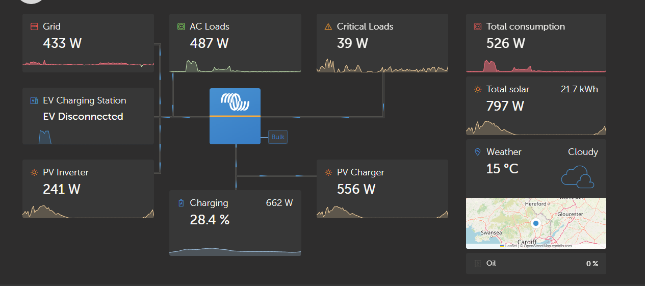
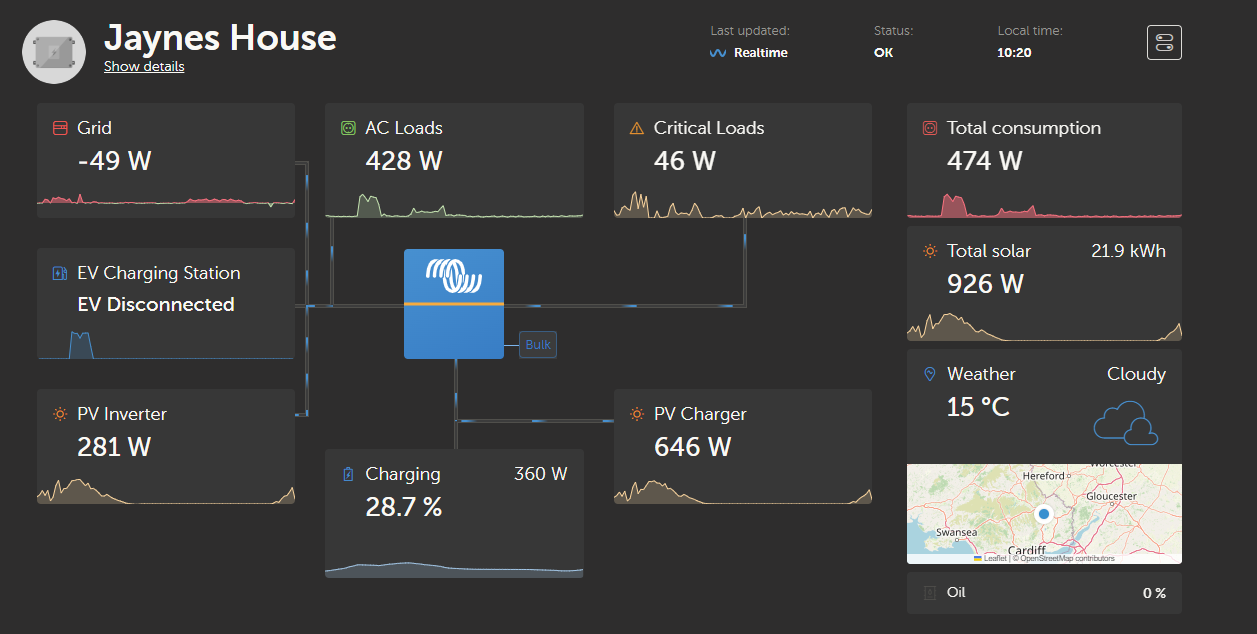
I use external et112 to monitor grid and most of my loads are on grid side (ACIN)


this weekend I added a second multiplus in parallel (equal wire lengths, same model etc)

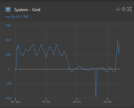
All works perfect at night and under higher loads but on lower load it uses grid.

To me this screams peak shaving. And I did reduce the dvcc cirrent limit and added limit inverter power in ess while testing .

I've now removed those limits to try resolve the problem.


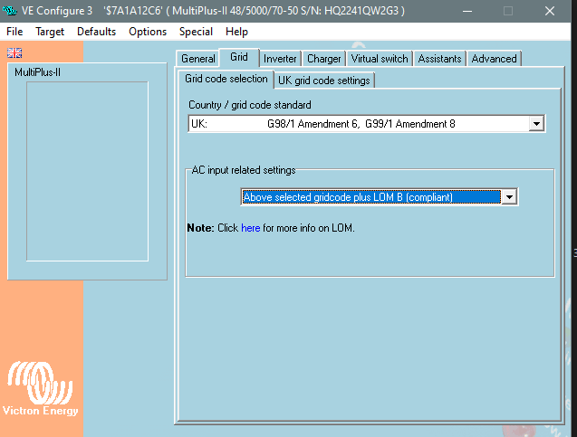
Anyone think of any other cause or is it likely peak shaving? Anything in veconfig I've maybe missed?

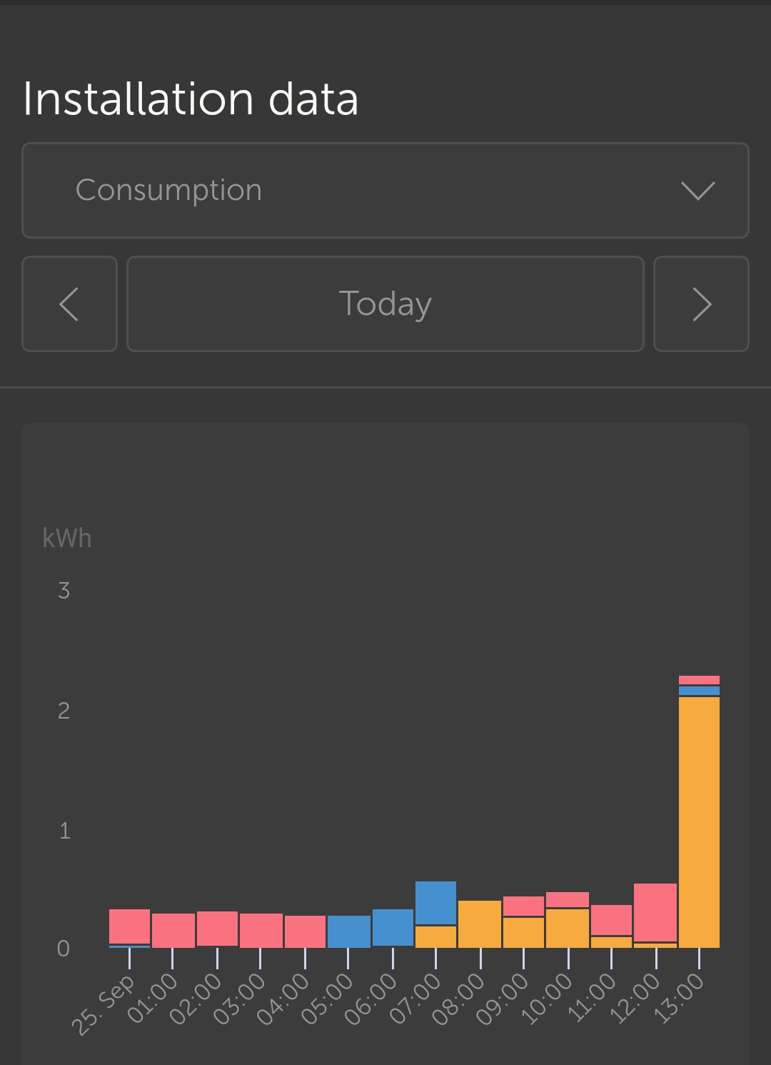
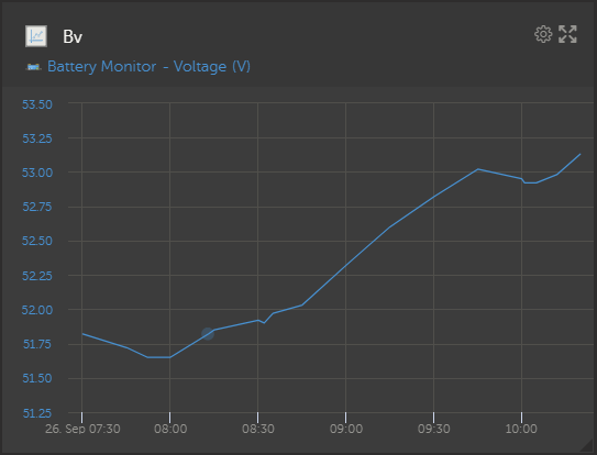
I have schedule charging overnight due to cheap power hence grid usage overnight but doesn't explain grid usage during the day starting st 9am ish.

Higher loads seem to sort the probelm which makes me think peak shaving but could it be an anything else?


screenshot-20230925-134634.jpg


ESSmultiplus in parallel
2 |3000

Up to 8 attachments (including images) can be used with a maximum of 190.8 MiB each and 286.6 MiB total.

6 Answers
Alexandra avatar image
Alexandra answered ·

@matt1309

Peak shaving is where the inverters assist the grid not the grid assisting the inverter. So it is more likely another issue.

Is it obeying the grid set point?

I can't see the battery SOC. Is it stopping production for lower loads when the battery is full? Is it an intelligent can connected battery?

How equally is the load shared under higher loads.


2 |3000

Up to 8 attachments (including images) can be used with a maximum of 190.8 MiB each and 286.6 MiB total.

matt1309 avatar image
matt1309 answered ·

Hi @Alexandra


It's happened again. It seems to correspond with a spike in solar:

Any ideas what's causing this?

Just a note schedule charging is enabled up to 25% between 12am and 5am.


1695719739849.png


1695719766701.png

1695719781146.png

Thern after setting grid setpoint to -600 and then back to 0 it returns to normal:


1695720045289.png


1695719739849.png (127.9 KiB)
1695719766701.png (26.3 KiB)
1695719781146.png (24.8 KiB)
1695720045289.png (139.1 KiB)
8 comments
2 |3000

Up to 8 attachments (including images) can be used with a maximum of 190.8 MiB each and 286.6 MiB total.

Alexandra avatar image Alexandra ♦ commented ·

@matt1309

Your battery (is disconnecting) probably the contactor is opening and closing?

0 Likes 0 ·
matt1309 avatar image matt1309 Alexandra ♦ commented ·

@Alexandra

Non that i can think of.

BMS limits are way larger than those limits. No signs of notifications in GX device or VRM. And battery voltage doesnt seem to dip. It's linked to solar somehow but no idea how/why?

1695720409203.png


0 Likes 0 ·
1695720409203.png (21.4 KiB)
Alexandra avatar image Alexandra ♦ matt1309 commented ·
Battery voltage on the battery monitor is read before the contactor usually so would not always be an indicator of the contactor being open since it reads its own pack voltage.


A spike in mppt battery voltage is often caused by solar production not having anywhere to go.


What grid code/LOM are you running? The spike back to grid seems to start when solar wakes up. Sorry not all that clear from the graph. Just trying to clarify.

0 Likes 0 ·
matt1309 avatar image matt1309 Alexandra ♦ commented ·

@Alexandra

so there's a contactor in the multiplus? You're not referring to something on BMS side? I've checked BMS no warnings/notifications.


The odd part is I've not added any additional solar. So if old system can handle it then surely new should also. Its definitely solar linked. Solar's died down now and the grid usage is 0. Similarly if i set grid set point to -600w ish it will go to -600w.


I wouldve expected error messages if the solar had no where to go right?

Grid code:

1695723525664.png

0 Likes 0 ·
1695723525664.png (30.4 KiB)
matt1309 avatar image matt1309 matt1309 commented ·
I've got one more guess I'm trying but need solar to peak to check it.

I've made the mistake of assuming I can not wire in ACOUT of just the one inverter (as i didnt need the additional power on ACOUT only ACIN). I'm guessing this is not allowed.


Once the sun peaks again I should know (could be awhile I live in Wales...)

0 Likes 0 ·
Alexandra avatar image Alexandra ♦ matt1309 commented ·
I was referring to the battery side. I am not totally familiar with the BMS you are using.

Also just spit balling places to look.

The BMS might not be warning about the open contactor. It would be something you would need to physically catch happening. Very few BMS are set up to warn about opening the contactor and reporting it. Does it log when it opens and closes?

No, the multi does it have a contactor on the DC.

And no there would be no errors on the mppt either. The voltage is within tolerance.

The inverter set up being the thing changed is more likely to be related to the issue.

Did you use premade comms cables? I assume they are all on the same firmware etc. All components updated?

It looks like when solar wakes up and the solar/grid mix is starting up, there is a hiccup. Do you have feed in from DC switched on?

0 Likes 0 ·
matt1309 avatar image matt1309 Alexandra ♦ commented ·

@Alexandra

Disconnecting ACOUT did not resolve the issue. Sun peaked and it happened again.

BMS has a tab for alerting for errors so should have at least something notable in it. Smart shunt is wired after BMS but before inverters/MPTT, so i should see a dip in voltage if contacts are closing right?


I made the veBus cat 6 cable, could it be that. I made both ends off following type B colours. They dont need to be one end A one B do they?

Yeh same firmware, updated both before install. 506 I believe.

I do have DC feed in enabled however limited at 3.4kw. I'll try keep an eye on that. That number wouldnt need to double now there's two inverters would it?


0 Likes 0 ·
matt1309 avatar image matt1309 Alexandra ♦ commented ·
@Alexandra

I've tested with premade cable and no change. I was next to. Inverter this time. When solar ramps up there's a slight change in the humming sound of new inverter. When I use ct clamp it's drawing power from grid of the excess amount.

However old/master inverter is behaving as expected/not inverting at all.


I'm at a loss tbh. Any ideas what could cause this. I've saved vecinfig file down and loaded into each inverter so in theory they're identically configured?


To fix the issues I need to load the system either by turning load on or setting grid setpoint to negative.

0 Likes 0 ·
matt1309 avatar image
matt1309 answered ·

Just in summary:


1x multiplus ran fine for months. Only changes made was adding a new unit. I've returned all settings to exactly the same as what they were previously. Only difference is I've added them to both Multiplus units.

During the night the system works exactly as expected. At high loads again it works as expected. Similarly if i set grid setpoint sufficiently negative it seems to correct the system. However as soon as solar spikes it returns to this behaviour of passing through near all power from grid.


I did think maybe the ET112 wire from solar is getting interference from AC lines but I've moved around a little and see no obvious changes.


A few odd things to check. I only have one multiplus connected to loads on ACOUT side but both on ACIN. I've now removed the ACOUT connection all together so neither are connected to loads on ACOUT. As was worried this was the cause.


When adding settings to VeConfigure. Both multiplus have indentical settings/assistants, is that correct?

2 |3000

Up to 8 attachments (including images) can be used with a maximum of 190.8 MiB each and 286.6 MiB total.

nickdb avatar image
nickdb answered ·

With an upgrade make sure the new multi is master, not the old one.


3 comments
2 |3000

Up to 8 attachments (including images) can be used with a maximum of 190.8 MiB each and 286.6 MiB total.

matt1309 avatar image matt1309 commented ·
I'll give this a go tonight. It seems like the new unit is causing the issues. CT clamp on new one it's drawing 500w when it should be nil. It seems to kick in when solar increases above a threshold. Not quite sure what that threshold is. Also not sure if it's link to amount of power hiitting the battery or amount of power from AC coupled PV.


But it's the opposite direction to what makes sense. when solar gets above x watts it draws from grid

0 Likes 0 ·
Alexandra avatar image Alexandra ♦ matt1309 commented ·

@matt1309

Was coming here today this. The new one should be the master
0 Likes 0 ·
matt1309 avatar image matt1309 Alexandra ♦ commented ·
Just out of curiosity why is this? I've yet to find a threshold but it seems linked to the amount that's going into the battery. I cant think why that would cause the multiplus slave to draw extra power from grid though. I suspected induction on data cables but none are that close to AC power. The closest one is the AC coupled PV Rs485 cable but issue seems to remain even with that PV disconnected.


I'll redo vebus tonight and swap them. I'll report back after that.

0 Likes 0 ·
matt1309 avatar image
matt1309 answered ·

Hi @Alexandra @nickdb


I've tried what you suggested. Made the new unit the master. At first i was hopeful. To test it i increased grid setpoint to 1.5kw. For some reason the system was now outputting circ 400w less than the grid setpoint at 1200w but if that was the only issue i'd have been happy.


However that was just the beginning. It was particularly bad when I would change grid setpoint from say 1500w to 0w.

There'd be a distinct single humming noise from the new unit which I've come to learn is the cue for whatever is wrong with it to "turn on".

I've tried monitoring amperage on both AC and DC side when this occurs and it seems to be all over the place (both AC and DC). Almost like the new unit turns off/stops communicating but it doesnt shutdown like it would if you used the switch ie no warning lights or clicking sounds just low amps


Going from 0 to 1500w. The new unit seems to ramp up in amperage faster but then the load is balanced equally between the two.


Going from 1500w to 0w. The old unit sounds like it's really pumping out power. GX device hits -3000w grid output and then the old unit stops sounding like it's working hard and everything settles back down acting normal.

I dont know enough about the internals of these inverters but to me it now seems like there's some sort of faulty sensor in the new unit. Best case scenario it's out by 400w on it's target. Worst case it sounds like something terrible is happening to old unit.


I've converted back to single unit and running the old unit as before.


Is the behavior I've described above typical of an unbalanced pair of inverters. I was quite careful to ensure the wire runs were of the same length, both on AC and DC side.

When purchasing the new unit I spoke to the technical team at the distributor I purchased the unit from ensuring not just the same hardware/model number but also similar in age. (bought original from them also)

I thought unbalanced inverter symptoms would present itself in a less sporadic way?


The issues seems only to occur on charging. Discharging the battery is absolutely fine hence why I've only noticed the issues during the day and only been able to replicate at night by adjusting grid setpoint. Discharging the inverters seem well balanced.


I'm at a loss tbh. Might try the new unit in Standalone mode just for my sanity/hopefully to prove it's definitely a fault with the unit rather than the configuration I've set. However it's defeated me tonight, so I shall try again tomorrow.

4 comments
2 |3000

Up to 8 attachments (including images) can be used with a maximum of 190.8 MiB each and 286.6 MiB total.

nickdb avatar image nickdb ♦♦ commented ·

What is the first 4 numbers of each serial number?

What is the gauge and length of ac in/out cabling of each inverter?

Have you checked the output of each under load with a clamp meter?

0 Likes 0 ·
matt1309 avatar image matt1309 nickdb ♦♦ commented ·

Hi @nickdb


I just checked both units appear to run fine in standalone so it must be in unbalance/incompatible somewhere. The VeConfig configuration file I've saved down and loaded onto each, when i ran in parallel and standalone so I thinking it might not be config and is an imbalance somewhere. I just assumed if it was unbalanced charging it would also be discharging. However discharing seems fine, runs without issues at night.


I tested under 4kw (all loads on ACIN side/grid parallel). Discharging battery it performs fine. I was getting 48 and 47.8 DC side.

Both inverters SNs start with HQ22.

I'm using 6mm cable but limited both inverters to 32amp (on 32amp RCBOs).

I have just noticed that the 6mm cable has come from two different providers. Could that really make a difference? Same twin and earth cable, i only noticed due to slightly different colour insulation.


When charging at low amounts it seems normal it's when the charging rate increases the behavior becomes unusual. Must be in imbalance I just dont really know where to begin to tackle it.

0 Likes 0 ·
nickdb avatar image nickdb ♦♦ matt1309 commented ·

Is your AC cabling very short? Parallel systems don’t like that, it can cause interesting behaviour, but you would usually be able to measure an imbalance with a clamp meter.

0 Likes 0 ·
matt1309 avatar image matt1309 nickdb ♦♦ commented ·
Not really. I'd say about 2m. (didnt measure exactly just ran the one and cut another the same length as the first).

Would being on seperate RCBOs cause a difference rather than single RCD plus different MCBs?

I've noticed when I first turn on both inverters I get #3 Expected devices error, however I assumed this appeared as i turned on one invereter just before turning another on.


If i do one final test what would be the best procedures?

1. Run in parallel.

2. set grid set point large to charge battery measuring AC and DC current?

3. set grid setpoint back to 0 measure current on AC and DC side.

4. set grid setpoint negative to discharge battery measuring AC and DC current.

5 back to 0 measure again?


I'll try once more but from what I've done so far test 2 and 3 have issues with 4 and 5 acting normal.


0 Likes 0 ·
matt1309 avatar image
matt1309 answered ·

Does the fact discharging works and charging does not limit my search area? I'm about to start messing with ac wire lengths under the assumption that charging being st fault is more likely due to ac side limitations?

Anyone know enough abiht internals to comment on this?

Similarly does the fact one uni has 3.5mm current sensor vs the terminal sensor impact anything? Distributor has confirmed serial numbers are a match/OK for paralleling. The one unit has been running longer but I wasn't expecting such unstable behaviour.

2 comments
2 |3000

Up to 8 attachments (including images) can be used with a maximum of 190.8 MiB each and 286.6 MiB total.

palom170 avatar image palom170 commented ·

Did you fix the trouble ? Is the parallel system working properly ?

Thanks in advance.

0 Likes 0 ·
matt1309 avatar image matt1309 palom170 commented ·
No I did not. In the end I put it down to the age difference of the units after checking all other variables that I and my distributor could think of.


In the end I returned the new 5kva model I'd bought and exchange for 10kva and then sold my old 5kva to a friend

0 Likes 0 ·