question

sersurf avatar image
sersurf asked

Question for Victron Energy regarding the SPR00090 retrofit kit

victron-fan.jpg


My German dealer (Panda-Solar) has rejected my request to the SPR00090 retrofit kit, since I have the units with the relatively new Serial Numbers.

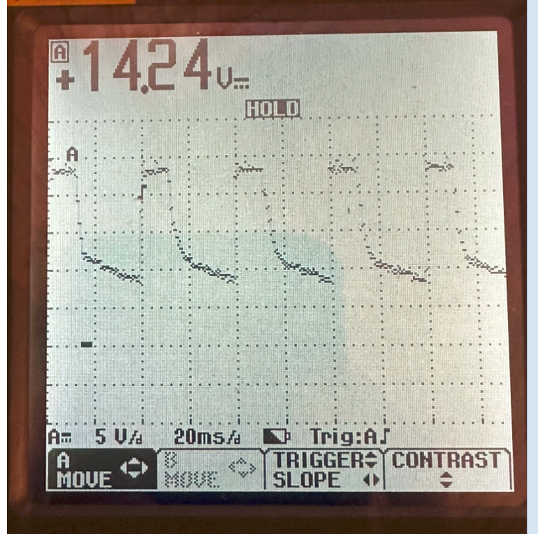
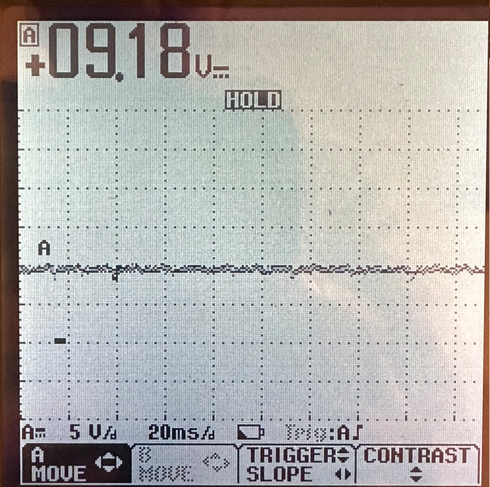
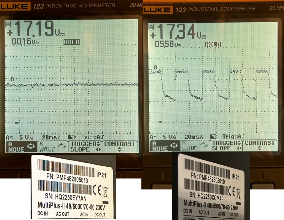
The picture shows the voltage trace measured directly at the fan connector at low RPM.

The picture is the proof that:

The unit HQ2250EY7AN has the issue factory solved.

The unit HQ2250XCM4P has the 25Hz issue unsolved.

your Document regarding the retrofit kit says that only the units build before HQ2224 are affected, but this is not true.

Please provide the official statement that the unit HQ2250XCM4P entitled to have retrofit kit been installed. I need this statement for the communication with the dealer.

Regards,

Update 24.09.2023:

Please read my report (pdf attached)Further investigation of the 25Hz fan control issue on the HQ2250XCM4P unit.pdf

Multiplus-II
3 comments
2 |3000

Up to 8 attachments (including images) can be used with a maximum of 190.8 MiB each and 286.6 MiB total.

kevgermany avatar image kevgermany ♦♦ commented ·
Did you show the dealer these images?

Perhaps @Guy Stewart (Victron Community Manager) can help.


0 Likes 0 ·
sersurf avatar image sersurf kevgermany ♦♦ commented ·

Yes, of course I did. But the dealer insist that all new units already have the necessary modifications at the factory. I am not sure that the dealer technically understands that the measurement shown on the right picture is the proof that at least some units do not have the required modification.

0 Likes 0 ·
sersurf avatar image sersurf commented ·

Further investigation of the 25Hz fan control issue on the HQ2250XCM4P unit.pdf

This is the update on my initial question.

The retrofit kit can not help. Please read my technical report (attached pdf) with the explanations why it will not help.

The questions to Victron Energy that are still actual:

1. How many units of type 3 (see my report attached) have been build and sold?

2. Can you trace them with the serial numbers?

3. What can you offer to the customers having these type 3 units running in the field in order to solve terrible 25Hz fan noise issue at low RPM?

0 Likes 0 ·
6 Answers
mvader (Victron Energy) avatar image
mvader (Victron Energy) answered ·

Hi all, and thank you to especially @Sersurf for being so persistent and helping us to get to the bottom of this.

The issue with the unit @Sersurf that you sent us, and quite many more, is that a mistake has been made in its eeprom initialisation, in our factories.

The solution is to update the firmware to v507. Full details in this PDF:

2023-11 - MultiPlus-II firmware v507 with fan control improvement v2.pdf


4 comments
2 |3000

Up to 8 attachments (including images) can be used with a maximum of 190.8 MiB each and 286.6 MiB total.

kevgermany avatar image kevgermany ♦♦ commented ·
Are the multiplus units in EasySolars also affected?
0 Likes 0 ·
mvader (Victron Energy) avatar image mvader (Victron Energy) ♦♦ kevgermany ♦♦ commented ·
Hi Kevin, no. If they were, then they'd be listed in the PDF.
1 Like 1 ·
kevgermany avatar image kevgermany ♦♦ mvader (Victron Energy) ♦♦ commented ·
Just checking, you know how I am ;-)
0 Likes 0 ·
beat avatar image beat commented ·

Hi @mvader (Victron Energy) ,

Thanks for the improvement. It makes a big difference, even if not yet "quiet" or even "comfortable" (whistles and other unconfortable fan noises, there is btw an awesome document in how to engineer extremely quiet fans and heatpumps barely without exra-cost here http://www.laerm.ch/dokumente/laermsorgen/waermepumpen_bae.pdf REALLY awesome guide for your future products).

BTW The XLS file with serial numbers in Victron Professional (finally found in firmware, only under 27 120VAC Products...) gives a "404 not found" on the web.

0 Likes 0 ·
Alexandra avatar image
Alexandra answered ·

@Sersurf

54221-2023-05-mpii-retrofit-kit-to-reduce-low-rpm-fan-no.pdf

Is the official statement.

I donhave a few questions about the tests.

Are the units at the same temperature and load? (since it is fan speed related and that is load and temp related.) Are they in stand alone or in parrallel?

Can you share a few more details about the test conditions?


1 comment
2 |3000

Up to 8 attachments (including images) can be used with a maximum of 190.8 MiB each and 286.6 MiB total.

sersurf avatar image sersurf commented ·

I am aware of this pdf document. But this is exactly where the problem is.

Victron claims that all MP2 units after HQ2224 production week have the required modification of the fan driving circuitry already onboard.

But my measurement shows that this is not true.

The picture on the left shows how it should look like after modification.

If the system requires more cooling capacity from the fan, it simply increase the DC-voltage on it.

The picture on the right shows how it was before the design change.

If the system requires more or less cooling capacity from the fan, it changes the duty-cycle of the 25Hz PWM signal applied to the fan. And this sounds really terrible at low RPM.

It doesn't matter if the units are in parallel or standalone.

The measurements are taken at partial load, the units are loaded such a way that the system commands the fan less than 100% RPM in both cases.

The voltage traces are taken directly across the fan connector.

0 Likes 0 ·
pyrorider avatar image
pyrorider answered ·

I am curious why another seller (offgridshop) offers the pcb for 37€ if victron provides them free of charge to the distributors

2 comments
2 |3000

Up to 8 attachments (including images) can be used with a maximum of 190.8 MiB each and 286.6 MiB total.

luphi avatar image luphi commented ·

probably to compensate the administrative effort

0 Likes 0 ·
sersurf avatar image sersurf commented ·
The distributor can order the kit free of charge to be assigned to the "old" (before HQ2224) production week code, as per pdf statement from Victron.

For me the question is not the 35-40Euro for the kit.

As the electronics-design engineer with more than 20 years of experience in switching-mode power supplies I can build the solution similar to the retrofit kit myself. It is relatively easy.

The issue is that Victron still continues to build the units having 25Hz PWM fan driving circuit, but doesn't instruct the distributors to offer the retrofit kit in such a cases.

0 Likes 0 ·
luphi avatar image
luphi answered ·

are there any visible differences on the PCBs to determine if the fix is factory included or not?

Might be more reliable than the serial numbers

4 comments
2 |3000

Up to 8 attachments (including images) can be used with a maximum of 190.8 MiB each and 286.6 MiB total.

sersurf avatar image sersurf commented ·

Good question.

From what I can see without disassembling the unit and disconnecting the PCBs from each other, no there are no visible differences in both units. Probably I could find it, but I need to go deeper for this.

The "factory fix" is not the same as retrofit kit offered.

It looks like there is a high frequency DC-DC buck stage (https://en.wikipedia.org/wiki/Buck_converter) at the output which should provide the smooth regulated output voltage, but in one of my units it is somehow not configured to operate properly and still has 25Hz PWM output like old units.

0 Likes 0 ·
luphi avatar image luphi sersurf commented ·

maybe @Guy Stewart (Victron Community Manager) can shed some light here.

My multis are HQ2237 and HQ2238. I find them quite noisy, but I 'don't have any reference.


0 Likes 0 ·
sersurf avatar image sersurf luphi commented ·
Do you know how to contact him? I do not see possibility to send him a personal message over this platform.
0 Likes 0 ·
luphi avatar image luphi sersurf commented ·
I hope, the mentioning above will ring a bell ;-)
0 Likes 0 ·
mvader (Victron Energy) avatar image
mvader (Victron Energy) answered ·

Hi @Sersurf ,


Quite mystery indeed! And we’ll sort this.


We’ll check, using those serial numbers, what happened.

Until your message, I also didn’t know any better than that per serial number X, the production was updated according to the change note.


I’ll get back to you.


Meanwhile, ofcourse you can get that retrofit PCBA for free. Quickest would be you ask your distributor? Perhaps shown them this thread?


We can also put one in the post.


Best regards, Matthijs

12 comments
2 |3000

Up to 8 attachments (including images) can be used with a maximum of 190.8 MiB each and 286.6 MiB total.

sersurf avatar image sersurf commented ·
Hi Matthijs,

Thank you for your reply. I will forward it to the distributor.

In case your factory traceability data will not allow to identify the issue, and you would need any further assistance from my side to compare a "good" one with a "bad" one in details (because I have both), just let me know.

I am a designer of the switching-mode power supplies and other electronics with more than 20 years of experience.

I have compared the PCBs visually, and could not identify any difference in the hardware.

The sticker labels on the MCU chip show the same HEX file name.

The firmware in both units is the same, 2623506

By the way, the original logical 25Hz PWM signal, commanding the fan speed is coming from the microcontroller, or the source of this signal is some hardware circuitry on the aux power supply PCB?

I believe this is important for you as well to find out how many units sold with newer serial numbers could be affected as the one I have.

Regards,

Sergey

0 Likes 0 ·
mvader (Victron Energy) avatar image mvader (Victron Energy) ♦♦ sersurf commented ·

hi @Sersurf , my apologies for the delay; I lost track of this issue.

We traced this back to indeed be a production error. And that error is such thta installing the SPR00090 retrofit kit doesn't fix the issue.


We would really prefer to have the unit back to know for sure / see it on the bench. Can you arrange an RMA via your dealer? Please let them add a remark that Victron has said that they want the unit (HQ2250XCM4P) back for R&D analysis, and that a new unit is to be supplied under warranty.

Thank you, Matthijs


2 Likes 2 ·
sersurf avatar image sersurf mvader (Victron Energy) ♦♦ commented ·

Hi Matthijs,

Today I have sent the unit HQ2250XCM4P with RMA 366.953 to Accusysteme Transwatt GmbH (German service center) as was instructed by my dealer, so you can check the status of the investigation.

I hope it will not take too long time to get the replacement unit. Actually the unit was running OK with my own "retrofit kit" (see below). And the dealer believes it might take 10 days or so for the failure analysis, while my ESS is missing one Multiplus...


Regards,

Sergey


0 Likes 0 ·
mvader (Victron Energy) avatar image mvader (Victron Energy) ♦♦ sersurf commented ·
Hi @Sersurf , thanks! we received the unit today, now its being shipped to a different office so next week I should be able to give you more details.


Meanwhile: did you get the replacement unit? In most cases, the dealer should be able to give you a new one from stock immediately - no waiting time for 10 days.

0 Likes 0 ·
sersurf avatar image sersurf mvader (Victron Energy) ♦♦ commented ·

Hello Matthijs @mvader (Victron Energy) ,

I have received the new unit just yesterday. It was the long way through all the agents, dispite of the fact that I am living 3 hours to drive by car from your office. My dealer could probably manage it better, but we have just what we have.

If you can tell me a dealer in Germany that should react like you describe above, please let me know, I will consider it for the next purchase of the Victron product.

So, back to the unit and 25Hz issue:

The replacement unit is HQ2242D4GJW.

This morning I have connected the unit to AC and the battery. As the first step, I have updated the firmware using VictronConnect from v498 to the actual v506, because I need two units in my ESS and I want to be sure the FW is the same in both, based on your ESS manual.

Configured both inits without any issues, started ESS and.........same picture on the Fan connector at low RPM:

hq2242d4gjw-still-25hz.png

My first idea was "does the FW update makes the Fan driver crazy?"

But I did exactely the same steps with another unit (HQ2250EY7AN) two monthes ago, and it's Fan runs smooth, no 25Hz modulation.

I still have my own "retrofit kit" that helps, but what is going on?

2 units from 3 that I have tested so far show 25 Hz modulation.

I hope you will find the root cause.

Regards,

Sergey

0 Likes 0 ·
sersurf avatar image sersurf sersurf commented ·

Hello Matthijs @mvader (Victron Energy)

I confirm the v507 Firmware changes the 25Hz modulation to the smooth voltage. The picture below shows the DC voltage applied to the FAN at low rpm. I hope my measurements were helpful to find a root cause and solution for this issue.

Regards,

v507fw.png


0 Likes 0 ·
v507fw.png (2.1 MiB)
mvader (Victron Energy) avatar image mvader (Victron Energy) ♦♦ sersurf commented ·
They were - together with your persistence - crucial.


Can I get in touch with you for a better thank you? You can send me a private message; or just an email; its guessable/findable

1 Like 1 ·
sersurf avatar image sersurf mvader (Victron Energy) ♦♦ commented ·

Hello Matthijs @mvader (Victron Energy),

I have sent an email to you last Wednesday late evening, not sure if you have received it

0 Likes 0 ·
sersurf avatar image sersurf mvader (Victron Energy) ♦♦ commented ·

Hello Matthijs @mvader (Victron Energy),

I have lost a communication with you over email since November 26. Did something happen/change that I should know about?

In any case I wish you a merry Christmas and a happy new year filled with health, wealth, and joy.

Sergey

0 Likes 0 ·
kevgermany avatar image kevgermany ♦♦ sersurf commented ·
I've notified via an internal channel. However due to holiday season, I'm not sure when there will be a reply.
0 Likes 0 ·
sersurf avatar image sersurf mvader (Victron Energy) ♦♦ commented ·

Hello Matthijs @mvader (Victron Energy),

I have lost a communication with you over email since November 26. Did something happen/change that I should know about?

0 Likes 0 ·
mvader (Victron Energy) avatar image mvader (Victron Energy) ♦♦ sersurf commented ·
Nothing to know, it was an issue on my side. I've reacted to your email just now. all the best and a good 2024!
0 Likes 0 ·
sersurf avatar image
sersurf answered ·

Analyzing the original Victron retrofit kit circuit

pic1.png

The schematic shown is just a sketch, some elements might be missing, the values of the ceramic caps are not shown, they are not important for the understanding how it works.

The output stage is 40 kHz buck converter having bottom-side Mosfet M3 (IRL530), Output Inductor L1, output capacitor C5 and top-side Schottky diode D3.

U2 OpAmp configured as the Saw-tooth ramp generator, U3 is PWM Comparator. Both are MC34072 OpAmps in one package.

The main Energy Tank is the large (2200uF 35V) C2 capacitor. The circuit around C2 is a kind of “soft start” for each pulse of the original 25Hz PWM signal, coming to the input.

At the beginning, the sum of R4+R3 resistors limits the charge current, after some delay M1 Mosfet shorts the R4 resistor, the current flows through M1 and R3, and after another delay M2 shorts the R3, connecting C2 capacitor directly to the input.

Issue number 1:

The output voltage applied to the fan is a linear function of the average input voltage (or input PWM duty cycle). My measurements confirm this in the range 20%-80%:

pic2.png

This is not quite correct. I would expect that the output power is a linear function of the input PWM duty cycle, because this would make the cooling capacity of the fan at low RPM equivalent to that without the retrofit kit.

Issue number 2:

This circuit works correctly only if there are no capacitance directly at the input (old Multiplus units, 25Hz-design failure), the only discharge resistor here is R7 (4K7). This makes the retrofit kit useless in the new Multiplus units, having 100uF capacitor at the output stage of the new fan driver, but still modulated by terrible 25Hz PWM (production failure).


I have assembled and tested my own “Retrofit kit” which can be used in both old and new units having terrible 25Hz PWM modulation.

pic3.png

The idea is very simple:

  • Put the energy tank (large capacitor) at the output.
  • Let the DC/DC converter, having input power limitation, charge the output capacitor.

What you see on the picture is probably overdesigned and oversized for this purpose; it is an isolated 25W flyback converter. I found and cut this piece of PCB from one of my existing designs at no costs.

Just two items I took from the Victron’s kit: Input and output connectors.

If I would design such a retrofit kit from the scratch, I would probably take another circuit based on non-isolated buck or buck-boost topology. My PCB BOM is about 7$, it could be 5$ if further optimized for a mass production.

Anyway, it works great for me.

With the peak current limiting function (primary side) a have “adjusted” the circuit for the particular fan power at maximum PWM and I got the output power proportional to the input duty cycle automatically:

pic4.png

Now the fan runs smooth at low RPM, no terrible 25Hz tractor sound.

Still waiting the answers from Victron how many units produced after HQ2224 are in the field having 25Hz modulation where the original retrofit kit will not help.

What can you offer to the customers having these units?


pic1.png (64.4 KiB)
pic2.png (28.9 KiB)
pic3.png (2.2 MiB)
pic4.png (39.7 KiB)
10 comments
2 |3000

Up to 8 attachments (including images) can be used with a maximum of 190.8 MiB each and 286.6 MiB total.

mvader (Victron Energy) avatar image mvader (Victron Energy) ♦♦ commented ·

> Still waiting the answers from Victron how many units produced after HQ2224 are in the field having 25Hz modulation where the original retrofit kit will not help.
> What can you offer to the customers having these units?


Correct. Units after HQ2224 still having 25Hz modulation will not be helped by installing the SPR00090 retrofit kit.

Any such unit needs to be handled individually, for now - returned for replacement. And if there are too many then we'll issue a repair instruction to our repair centers.

2 Likes 2 ·
beat avatar image beat mvader (Victron Energy) ♦♦ commented ·

Hi Matthijs @mvader (Victron Energy) ,

Thank you very much for handling this annoying noise issue and your answer! Does that mean, as you also asked here, that I too should ask my/your distributor for a warranty exchange for my 3-phase Multiplus II 5000/48 units behaving as described above (sudden on and off of very loud fans with only little change of speed) units ?

Here my 3 S./N.: HQ2225 RN DGG, HQ2229 AK 4CU, HQ2229 MW KAY.

And should I also tell them to return them to Victron for analysis ?

Best regards and wishing all of you a great week-end!


0 Likes 0 ·
pyrorider avatar image pyrorider commented ·
I really apprechiate the time and effort you put into this, I hope that victron will take this seriously and cooperate with you to solve this in a long term
0 Likes 0 ·
beat avatar image beat commented ·

Thank you very much for your thorough analysis!


My 3 MP II 48/5000 are HQ2225 and HQ2229, so I was feeling lucky as the issue was deemed as "fixed"), until I finally could test at higher power rates.

My MP IIs have an on/off behavior for the very loud fan. At around 1500 watts, after a minute or so, the fan starts at full speed. At 4500 watts, the fan is not feeling as noticeably faster or louder, maybe 10% or 20%.


Both HQ2225 and HQ2229 units behave same on/off behavior, despite being "fixed", and it's not a 25 Hz noise nor just white noise of air.


I definitely miss the low speed low noise normal behavior for fans nowadays, and that was the case in earlier models.

Btw, the fan model chosen is not great. Noctua 24V 2000 RPM industrial IP65 fan that is several magnitudes quieter than the unbalanced loud fan of the MP II, that a Victron reseller in Germany

And the rigid mounting of fan and transformer are "suboptimal" from a solidian noise transmission to the case perspective (including the service unfriendly fixing from the back disallowing in-place service).


The fan noise is loud that it's very tiring to stay in the room when the fan is on. To give an idea of the sound level, if you are at 1 meter from the MP II, you can't understand someone speaking clearly and moderately loudly at 6 meter distance. This really needs a fix or replacement.

0 Likes 0 ·
mac-the-knife avatar image mac-the-knife beat commented ·
Hi,


I have the units:

1) HQ2250 CC77F

2) HQ2250 9YHRM

3) HQ2250 EQR3D

I also find them very loud right from start-up of the fans at low output and no/hardly any change in noise level at full outuput.

How do I find out if i am really affected by the issue explained above and what could I do about it?

Should you require further information, please let me know.

Thank you for your help.

0 Likes 0 ·
sersurf avatar image sersurf mac-the-knife commented ·

Hi @mac-the-knife,

The issue explained here is just a 25Hz modulation issue at low RPM that should be solved after HQ2224 production date.

This topic doesn't cover lack of low RPM mode al light load. It might be a different story.

Unfortunately the description like "very loud right from start-up of the fans at low output and no/hardly any change in noise level at full output" will not help you, I guess.

You have to prove to your dealer that fun driver circuitry of your units doesn't work as it must work. I do not know how to do it without measuring the output of the driver with the oscilloscope.

If everything works as it should, you must see no voltage at all at the fan connector at light load. With increasing load and temperature, you should see the gradual increase of the voltage in the range from 12.... up to full 24V like on the very first picture (left picture) in my first message.

If you see the voltage jump from zero to any value above 20V in a single step, there might be something wrong requiring additional investigation of the issue, but again, this is a different issue, I haven't seen such a behavior in any of my units.

If you see the 25Hz modulation like on the right picture in my first message, the unit must be replaced under warranty. And this is what this topic about.

I understand that such a measurements require some knowledge in power electronics and it is dangerous if you do not know what you are doing. Risk of electrical shock!!! Unless you find someone with experience.

But even having 100% proof with such a measurements, the first reaction of my dealer was "Victron has improved the low RPM behavior of the Multis, it was even worse before". So, my first request was rejected till Matthijs Vader has confirmed here in forum it is the real issue.

I hope this helps.

Regards,


0 Likes 0 ·
lackland avatar image lackland commented ·
Regarding the relationship between input voltage and output voltage: this is not critical because the little circuit is inside the feedback loop controlled by the temperature sensor. If the heatsink is too hot, the firmware will increase the fan voltage until the correct temperature is reached.
0 Likes 0 ·
beat avatar image beat lackland commented ·

Sorry to ask as I'm very interested in this, @Lackland are you sure about that? and what is the kind of feedback loop mentionned? is it a PID ? The Multiplus II code isn't open-source, so it's not possible to know for sure without being at Victron development or having reverse engineered it or made extensive measurements?


I'm very interested in this, since the lower speed noise with v507 is much better (on the unit I upgraded) in level than the big noise that was there before, but is still very annoying, and I plan if that is not fixed during warranty, that once it is over to replace the loud fans with industrial Noctua with almost same flow but probably a different curve since they use less power...

0 Likes 0 ·
lackland avatar image lackland beat commented ·
Sorry, no insider knowledge. The observed behaviour (delayed fan response to increased current, faster fan at higher ambient temperature, etc) makes me pretty sure there's a temperature sensor involved.
0 Likes 0 ·
beat avatar image beat lackland commented ·

@Lackland yes, from what I read from Victron sources in here and in the documentation, there are at least 2 known temperature sensors, one on the power-electronics, and one on the big toroid transformer. But that doesn't mean that there is a feed-back loop regulating the speed to reach a given temperature. It looks more like a fixed curve temperature -> PWM cycle/frequency (that results into a median voltage on the fan) that simply got adjusted in v507 for particular hardware-different ("buggy"?) serial numbers (probably to take into account the added capacitor and maybe rise the frequency of the PWM), and sure to lower the minimum PWM cycle, if I read the v507 announcement right..


If there had been an auto-regulating feedback-loop regulator then probably we wouldn't have had this saga, and the Multiplus II would have been able to accomodate to any fan and almost any amount of dust.

But I'm not an insider either, just an observator and reader. So the above speculations might be wrong.

What's sure is that the vent of my unit is now making an audible whistling at medium speed and a rumbling at lower speed. We are still very far from white noise of a turbulent air flow and no-noise from a laminar air flow.


0 Likes 0 ·