question

pokerfjes avatar image
pokerfjes asked

Lithium battery bank composition

I know this question is bordering not relevant for Victron, but I may not be alone with this issue - and there are so many skilled techies here so I hope you can forgive me.
If I get this wrong I'm in for a very expensive detour on my camper build.

I have a Quattro 12/3000/120 which is going to be the heart of my offroad camper electrical.
I purchased it because I want to use VW e-Golf Lithium Ion packs for my battery bank, and was recommended to purchase the REC 4S ABMS as it is compatible with the Quattro, supporting the required voltage.
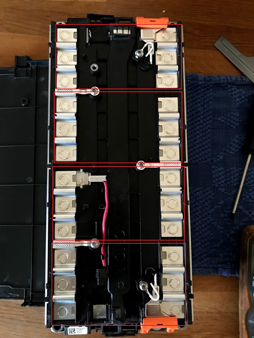
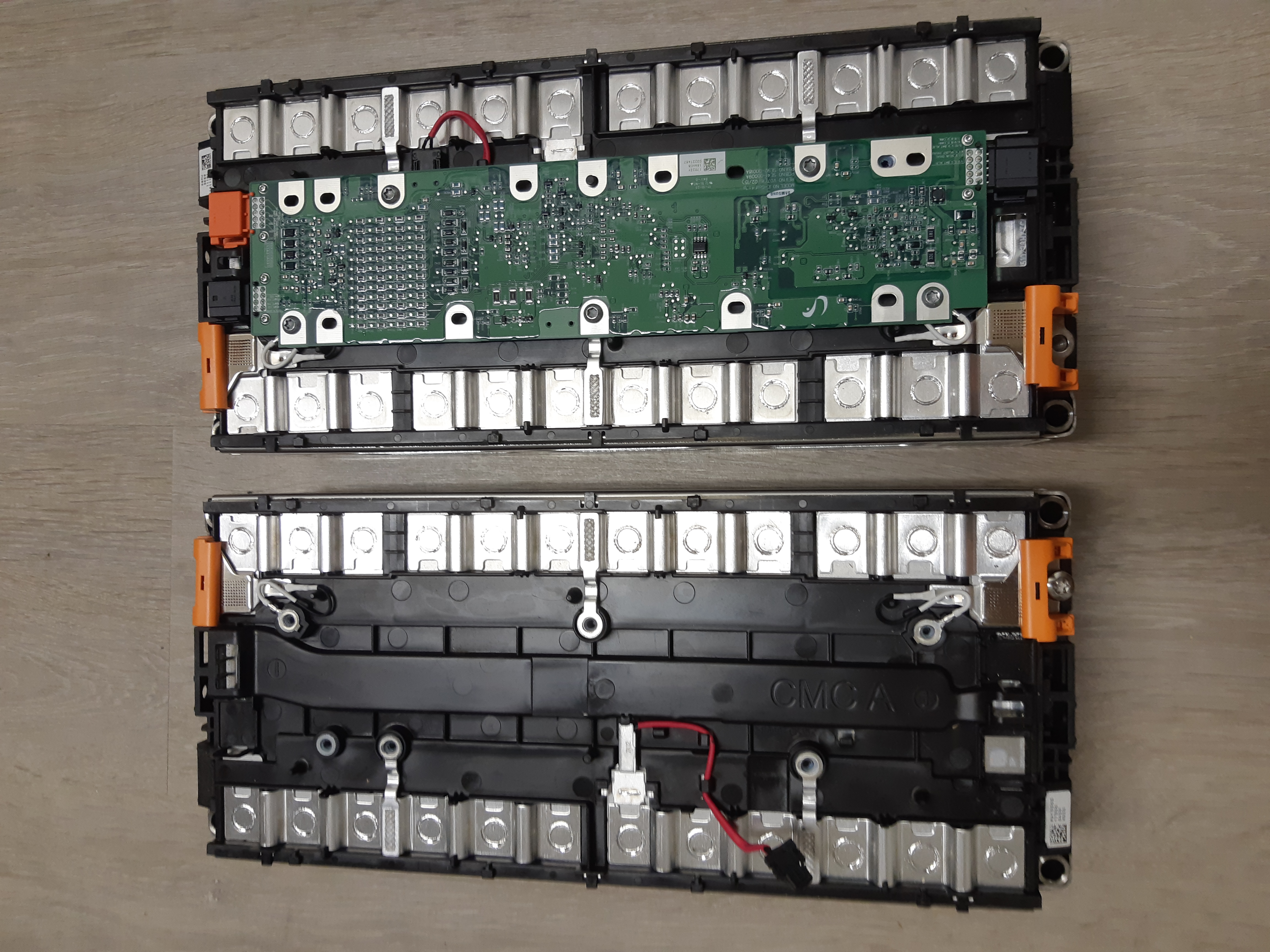
I want to build a bank around 10kWh capacity, and each VW module inside the VW battery is 4S3P, based on Samsung 37aH cells. I need 6 modules to reach the wanted capacity.

So far so good, but I fear I have an issue with battery bank composition and my expected result.
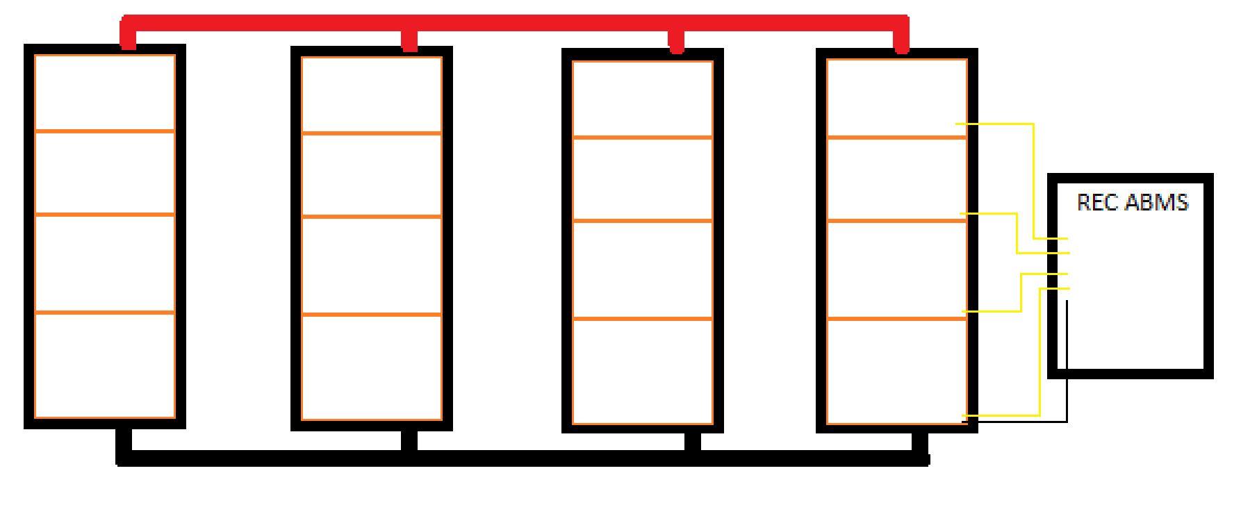
I purchased a couple of test modules the other day, and the guy says - sure - just connect the two modules in paralell, and connect the BMS to cells in one of the modules. He says the cells at the same parallell level will balance automatically across all 4S3P modules, and I will only need one BMS even if I add more of them. I'm in doubt though... since the 4S3P modules have no connection at cell level, how can they balance to the same level?

Attached are an image of one module from the VW e-Golf battery pack, and my 3rd grade level drawing of how I am supposed to connect this (according to the seller of the modules).

The individual 37aH cells are welded together and I suspect messing with that is going to cause more pain and cost more than I would like.

ANY advice is welcome at this stage.

battery
vw-4s3p-modul.jpg (391.6 KiB)
batterybank.jpg (86.6 KiB)
2 |3000

Up to 8 attachments (including images) can be used with a maximum of 190.8 MiB each and 286.6 MiB total.

2 Answers
AvB avatar image
AvB answered ·

Thanks for asking, I use same style batteries a lot on Victron. BMS is not optional, but absolutely required. Cells are easily permanently damaged by overcharging.,though this version does not easily explode. Yes I tried it a few times.

I highly recommend Rec BMS ,works very well with Victron. Also recomend safety relay as second safety layer.

picture below 1 battery with original bms and one without. I lack information to make original bms working.

indeed in parallel batteries you need to add the 3 wires to balance each pack internally.


3 comments
2 |3000

Up to 8 attachments (including images) can be used with a maximum of 190.8 MiB each and 286.6 MiB total.

pokerfjes avatar image pokerfjes commented ·

Thanks so much for responding. I am very interested in seeing some schematics on how you've connected these. You don't use a separate REC ABMS per module? The BMS would be 3x as expensive as a module.

The reason I chose the VW modules is because they are at least 30% less than the Tesla 7s packs when looking at cost per Wh. The Samsung 37Ah cells also have an amazing watt to weight and volume ratio.

0 Likes 0 ·
AvB avatar image AvB ♦♦ pokerfjes commented ·

Indeed 1 Rec BMS for entire battery bank. In a well running system all the batteries only need once in a while a few mAmps of balancing. Rec BMS has quite big resistors build in. The BMS thus is able to balance many parallel batteries.

Sorry don't have time to draw you a schematic. In fact I just took a look at your schematic and it is almost correct. The middle three wires have to also be attached to the other batteries. All cells in parallel must also be connected to the Rec BMS. Schematics in Rec BMS manual should tell you enough I guess and the support from REC bms is good.

1 Like 1 ·
pokerfjes avatar image pokerfjes AvB ♦♦ commented ·

The Rec BMS manual was not very clear on this case and their support actually said straight out that it was not possible. Must have been some misunderstanding then.

0 Likes 0 ·
kai avatar image
kai answered ·

I believe your suspicions are correct. For me the story started going sideways when the 4S3Ps are put in parallel before considering BMS. If each 4S3P pack on its own has its own BMS, and the BMSes talk to each other, sure I would say parallel them up.

The "balance" that would be achieved in the proposed scheme is only at the pack level. The cells inside the non-BMS'd packs will do their own thing according to chemistry. If the cells are well matched, then maybe the risk isn't too bad.

I can only offer some thoughts about possible approaches:

1) Reconsider whether you can live without the BMS and put in other controls (may be procedural, or maybe you sample the voltage of all cells and review them regularly).

2) BMS for each 4S3P... But this would involve engineering an interface between multiple BMS and the Quattro.

3) Is there a way of adding reliable connections onto the cells? If you can stack the packs vertically and connect up/down you turn the 4S3P into 4S(3*8)P. You wouldn't have to disassemble the packs but will need to physically support the packs externally with some structure. The cross connections need to be substantial to minimise cell voltage differences in each 24P group. Suggest you want to incrementally build and test this - this is not a typical way of approaching the problem and will cost if it goes wrong.

* I'm assuming you meant 8 packs to get to 10kWh.

All of the above will carry some level of risk that you probably weren't expecting to carry. Sorry to say that you may need to have a think about your resources to engineer a solution vs repurposing/ebaying the equipment you've already bought and chalking it up to a lesson.


8 comments
2 |3000

Up to 8 attachments (including images) can be used with a maximum of 190.8 MiB each and 286.6 MiB total.

mka avatar image mka commented ·

I agree with you a part from;

1) Reconsider whether you can live without the BMS and put in other controls (may be procedural, or maybe you sample the voltage of all cells and review them regularly).

with lithium batteries having a bms to manage the cells is more efficient and secure.

0 Likes 0 ·
pokerfjes avatar image pokerfjes commented ·

Thanks so much for your input. You've confirmed my suspicion.

The cells are most likely very well balanced. They are one of the latest generations Samsung SDI prismatic cells and I expect them to be of high grade. However, I do not wish to attempt to run them without a BMS.

I am looking into splitting the 4S3P module and create a 1S12P. This allows me to use the factory casing which is very rugged. I have a good welder at hand, but after a few hours of google, I want to avoid any kind of hedat applied to the cells.
I am currently investigating using conductive silver epoxy to bind the 4 3P packs in each module. As you can see from the image, there is plenty of area to make contact to a new connector and with some threaded mounts I can also apply some physical pressure to the connections.

I actually meant 6 modules to get 10kWh. 4S lithium-ion at 14.8v and 37x3 Ah = 1642Wh per module, but if I want to create 1S12P modules in the factory enclosure, I will have to create 1S24P and then serial them for a 4S24P setup which should result in a 12.7kWh pack.

0 Likes 0 ·
kai avatar image kai ♦ pokerfjes commented ·

right, I was for some reason thinking LiFePo. In which case yes, I would agree no BMS is not a good idea.

please let us know how you go with the epoxy, that's an interesting approach. Things like epoxy selection, control of bondline thickness and surface preparation would be useful for others wanting to do a similar thing.

0 Likes 0 ·
pokerfjes avatar image pokerfjes kai ♦ commented ·

The inter-cell connections are 22mm wide and 1mm thick. In my book that equals 22mm2 cross section, about 4 AWG. First task is to match that for the cell rearrangement. However, if I go to 24 parallell cells, I am toying with the idea of doubling the cell to cell connections with another 20mm2-ish bar across all the parallell cells. Not sure I will think it is such a good idea when I start gluing the addon bar to the cells, but its a theory for now. The silver epoxy is pretty expensive stuff, so I'm considering just using a regular silver paste between the new addon bar and the circular spots on each cell, with the silver epoxy ad the edge of the connection points. Expensive epoxy holds it down, slightly less expensive silver paste helps making the connection good.

0 Likes 0 ·
klim8skeptic avatar image klim8skeptic ♦ pokerfjes commented ·

The screws on top look like the points of attachment for the bms, and look like they could handle balance currents?

0 Likes 0 ·
pokerfjes avatar image pokerfjes klim8skeptic ♦ commented ·

You are correct, they are attachment points for balance leads. The - and + connection points are below the two identical orange plastic brackets.

But I need to group up 6 or 8 of these modules to get my desired kWh. I don't think I can connect the ABMS to pack 1, and connect pack 1 cell 1 balance to pack 2 cell 1 balance? Or can I?

0 Likes 0 ·
kai avatar image kai ♦ pokerfjes commented ·

From a balancing perspective tying all the balance wires for group 1 across all packs that should work (as alluded to by AvB in the other response).

The thing is when the entire battery is being used, how much current is going across those tied balance wires between packs? in a "typical" configuration there's a busbar there. If the cells are perfectly matched, the current should be low. As mismatch increases the current across the balance wires increases.

Whether you could get away with it... maybe?

0 Likes 0 ·
AvB avatar image AvB ♦♦ kai ♦ commented ·

In my opinion/experience you can get away with small balancing wires. Last few years I've build battery banks out of all kind of used car batteries and I typically use .75 mm² to connect battery packs in between for balancing. I typically only see a few mA's of balancing. This however only works if all the cells have same chemistry and best same capacity. But same capacity is less important from my testing.. I also tried different brands of cells and even different chemistry just for fun of testing. Most important is that batterypack1 and 2 and the rest... are both well connected on a busbar for negative and positive. Some people suggest adding fuses in balancing wires... But I have a love/hate relation ship with fuses as the problem than becomes who is going to check the fuses... so in short. I stay with .75mm² balancing wires and that gives enough resistance to limit high amps and has low enough resistance to take care of a few mA balancing currents. Better ideas always welcome.

0 Likes 0 ·

Related Resources

Additional resources still need to be added for this topic