question

mcdees84 avatar image
mcdees84 asked

Help explaining these amp current figures please

Hi all,

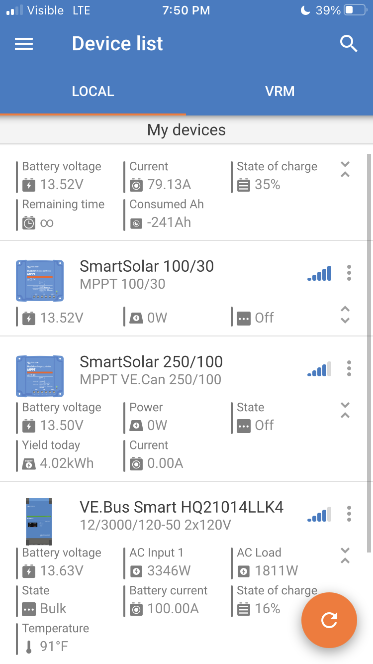
Can you offer some insight into my battery current here. I’m probably just ignorant, but it would seem to me, if my MPII is reading -133.70 amps, and my MPPT is adding 75.00 amps, my Smart Shunt should be showing only -58.7 amps. But as the screenshot shows, it’s reading -87.87 amps (29 amps more draw on the batteries than there should be)

Again, I’m probably just not understanding the intricacies and being too simple about it. Any help is much appreciated.


EDIT

Could it be that there is ~29 amps of dc power drawing at the same time? That seems hard to believe with just led lights in an rv

Multiplus-IIMPPT SmartSolarSmartShunt
2 |3000

Up to 8 attachments (including images) can be used with a maximum of 190.8 MiB each and 286.6 MiB total.

9 Answers
Matthias Lange - DE avatar image
Matthias Lange - DE answered ·

Any other DC loads?

Switch off the MultiPlus and see what's happen, deactivate the MPPT and see what's happen.

Maybe do the zero current calibration.

2 |3000

Up to 8 attachments (including images) can be used with a maximum of 190.8 MiB each and 286.6 MiB total.

mcdees84 avatar image
mcdees84 answered ·

img-4434.png
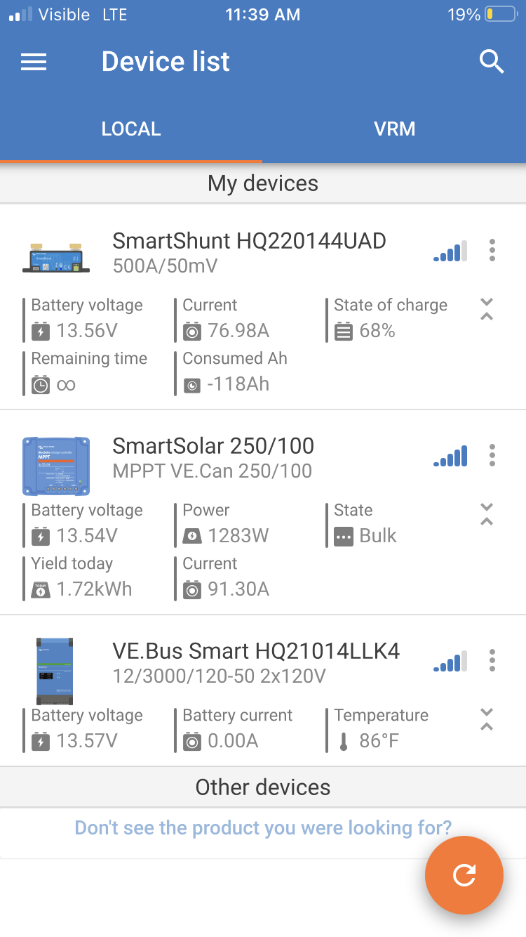
So I shut the mpii off and the numbers were still off. This time they were off by about 14.3 amps (see screenshot). This would make sense to me as I would expect about 10-15 amps of dc draw with my rv lights and other things on (which they are right now) - so if we zeroed out the discrepancy in this screenshot I think I’d be good.
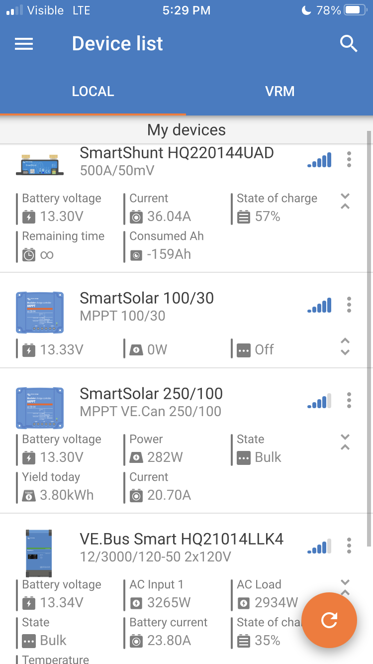

Is there a way to recalibrate the smart shunt? Would that even be the right calibration to run?


img-4434.png (176.3 KiB)
1 comment
2 |3000

Up to 8 attachments (including images) can be used with a maximum of 190.8 MiB each and 286.6 MiB total.

seb71 avatar image
seb71 answered ·

SmartShunt zero current calibration procedure is described in its manual:
https://www.victronenergy.com/media/pg/SmartShunt/en/all-features-and-settings.html#UUID-c5fc25c8-93aa-2f98-bfe3-46cb4dd6cc8d


Basically you turn off everything (don't disconnect the wires under load), then disconnect everything from the battery, except the SmartShunt. Easiest way is to disconnect the wire from the System/Load side of the SmartShunt.

Then use VictronConnect and check the SmartShunt current. It should be 0A (Zero Ampere).

If it is not 0A with everything disconnected from the battery, tap the "calibrate" button.

2 comments
2 |3000

Up to 8 attachments (including images) can be used with a maximum of 190.8 MiB each and 286.6 MiB total.

seb71 avatar image seb71 commented ·
Ninja'd.
0 Likes 0 ·
mcdees84 avatar image mcdees84 commented ·
Thanks! I’ll try this later today or tomorrow. My wife is using too many appliances to shut the rig down right now.
0 Likes 0 ·
kevgermany avatar image
kevgermany answered ·

Good suggestions above. Just to add, I'm constantly surprised by how much power my LED lights draw.

2 |3000

Up to 8 attachments (including images) can be used with a maximum of 190.8 MiB each and 286.6 MiB total.

mcdees84 avatar image
mcdees84 answered ·

Well, @Matthias Lange - DE and @Seb71 , I did the zero current test last night and there was no current running when everything was disconnected. So I didn’t calibrate.

I guess that leaves me to assume I’m pulling a whopping 25-30 amps of dc power? I guess I may just start flipping breakers on the distribution panel and see how low I can bring the dc consumption down.

Any other ideas? Thanks!

1 comment
2 |3000

Up to 8 attachments (including images) can be used with a maximum of 190.8 MiB each and 286.6 MiB total.

seb71 avatar image seb71 commented ·
Also check for bad contacts (loose or corroded) etc.. See if anything acts like a space heater.
0 Likes 0 ·
mcdees84 avatar image
mcdees84 answered ·

img-4446.png@Seb71 all connections look and feel good. Seems a consistent 25-29amp bleed of power somewhere (or just bad readings on the equipment not talking well to each other). I flipped every ac breaker off today and it had no impact on reducing the discrepancy (I.e., closing the gap on the numbers). So I’m guessing it’s got to be on the DC side somewhere (or bad equipment somewhere in the chain).

Tonight, we are in a Walmart parking lot so I had the chance to run the ac off the batteries. Cloudy day so solar didn’t help too much, though the numbers were wildly off again like the above pics in this thread.

Anyhow, I fired the generator up and now on the charge from both the MPII and solar, the numbers are still off - though less. 23 amps charging from MPII, 20 amps from mppt, and yet only reading 36 amps being input in the smartshunt - so off by -7 amps (should read 43 amps being input).

Any ideas? Maybe a bad smartshunt? Maybe a bad smart dongle for the MPII? Something else?

Thanks all for your help!


img-4446.png (200.9 KiB)
1 comment
2 |3000

Up to 8 attachments (including images) can be used with a maximum of 190.8 MiB each and 286.6 MiB total.

seb71 avatar image seb71 commented ·

Since this a vehicle installation, you most likely have some DC loads, too. Check those. Turn the inverter off while doing that, to take it out of the equation.

0 Likes 0 ·
mcdees84 avatar image
mcdees84 answered ·

Here’s another pic for reference. Now it’s just the MPII charging and there is still quite a difference between it and the smartshunt. img-4447.png


img-4447.png (186.0 KiB)
2 |3000

Up to 8 attachments (including images) can be used with a maximum of 190.8 MiB each and 286.6 MiB total.

kevgermany avatar image
kevgermany answered ·

Your screen shots show different battery SOC readings on the smart shunt and multiplus. The multiplus should be using the smart shunt values. It's in the Multiplus settings.

Also in the settings ensure SVS and SCS are turned on.

I'm suspicious of your wiring. Check the shunt battery wiring. All the batteries should have their negatives joined to the battery side of the shunt. There should be no other connections to the battery negatives. The batteries should be grounded to the chassis through the load side of the shunt, not from their negative terminals.

4 comments
2 |3000

Up to 8 attachments (including images) can be used with a maximum of 190.8 MiB each and 286.6 MiB total.

mcdees84 avatar image mcdees84 commented ·
I’ll check those settings tomorrow. They’ve always been a little off when the MPII was charging. I just chalked it up to them being slightly off when under heavy load.


Wiring is as you describe. Negatives are paralleled with one wire directly to the shunt which is then connect to the lynx distributor which is grounded to the chassis with 4/0 wire.

0 Likes 0 ·
seb71 avatar image seb71 commented ·

The multiplus should be using the smart shunt values. It's in the Multiplus settings.

Also in the settings ensure SVS and SCS are turned on.

He needs a GX device for that and he does not have one.

But he could use VE.Smart Networking to join the two SmartSolar MPPTs and the Smart Shunt into the same VE.Smart Network.

0 Likes 0 ·
mcdees84 avatar image mcdees84 seb71 commented ·
They are all in the same V.E.Smart Network.
0 Likes 0 ·
mcdees84 avatar image mcdees84 seb71 commented ·
I can’t do this with the mk3 adapter?
0 Likes 0 ·
mcdees84 avatar image
mcdees84 answered ·

Lastly, this is all running through a lynx distributor. any chance the power bleed could be somewhere in there? I ask because my MPII shows it’s sending, for example, let’s say 20 amps to the battery. The shunt only reads that the batteries are receiving 12 amps. The wiring goes from the MPII to the lynx then to the batteries. Something in that line has to be sucking some juice constantly and quite heavily.

All I have connected to the distributor is both mppts, the house lines to the main distribution panel, the MPII and the wire to the onboard generator to crank it up. I’m a little baffled here.

3 comments
2 |3000

Up to 8 attachments (including images) can be used with a maximum of 190.8 MiB each and 286.6 MiB total.

seb71 avatar image seb71 commented ·

the house lines to the main distribution panel

Disconnect these and check again.


and the wire to the onboard generator to crank it up.

What's that?

1 Like 1 ·
mcdees84 avatar image mcdees84 seb71 commented ·
Will check while removing lines to house panel. They are the pod/neg wires to start the generator.
0 Likes 0 ·
seb71 avatar image seb71 mcdees84 commented ·
Disconnect those too for testing.
1 Like 1 ·