question

Dragos avatar image
Dragos asked

3-phase Multiplus II 10000/48 issue when configuring the ESS assistant

Hi, All.

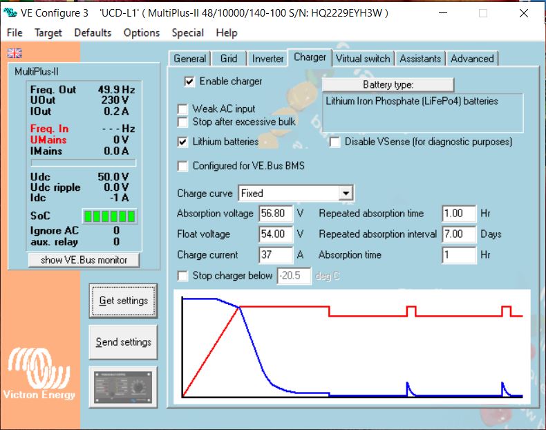
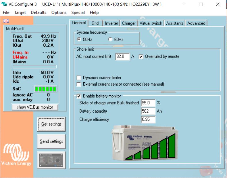
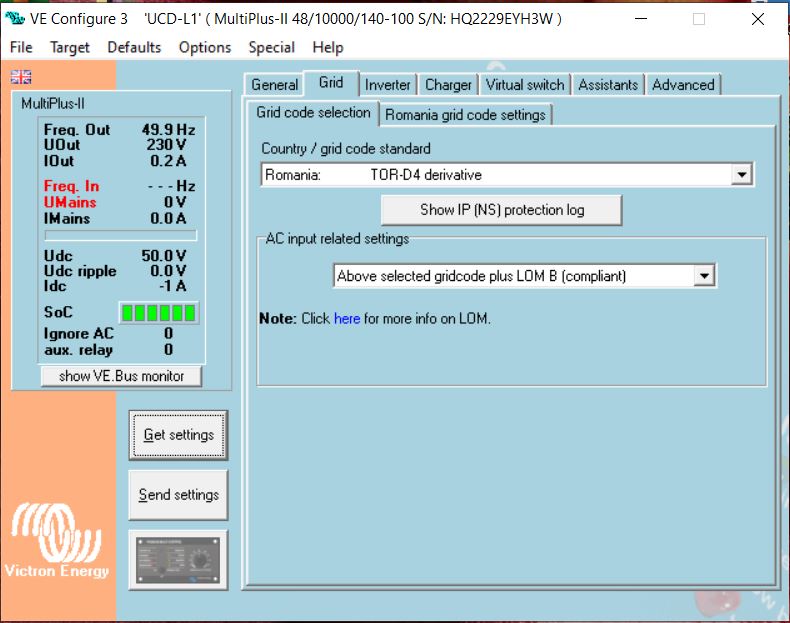
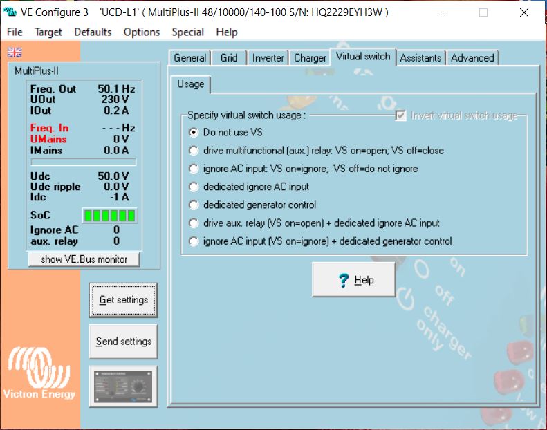
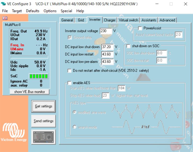
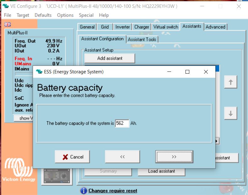
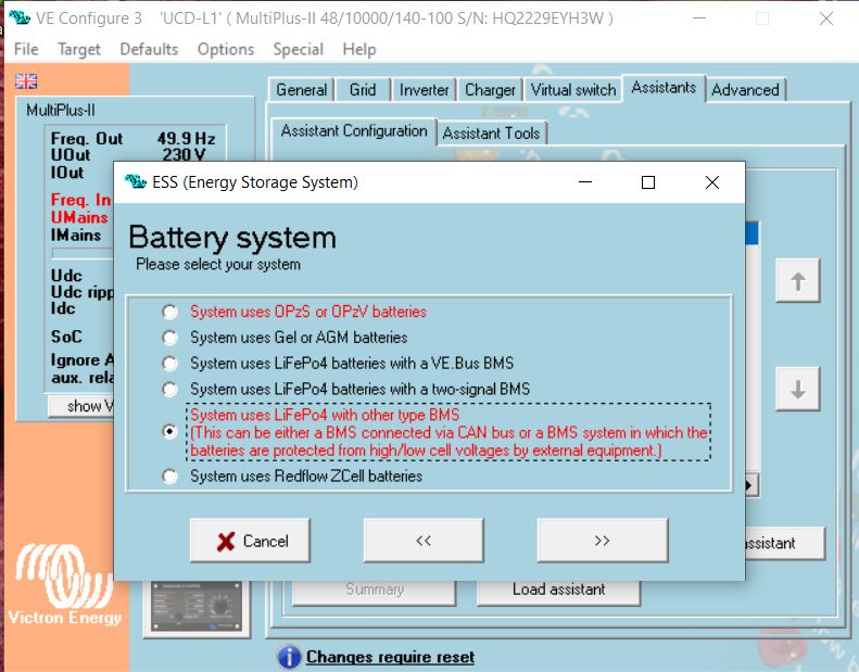
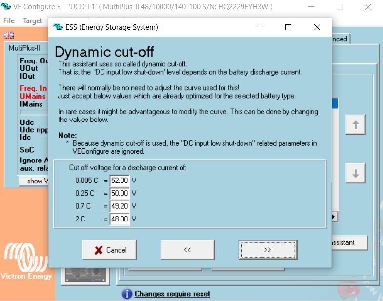
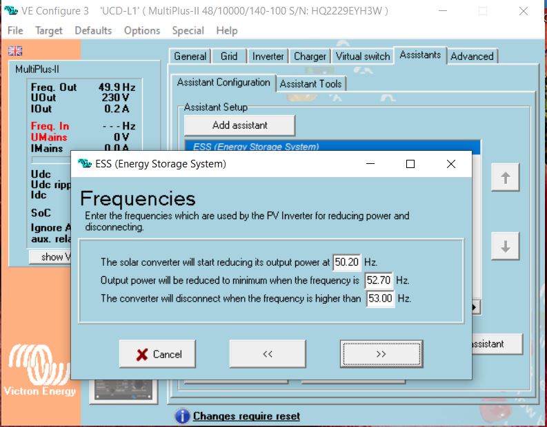
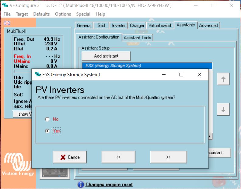
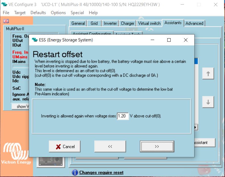
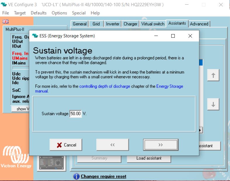
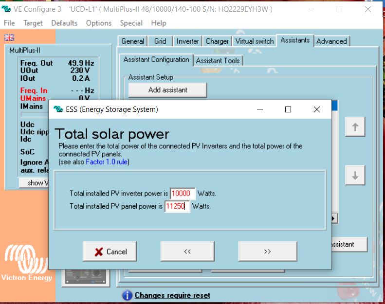
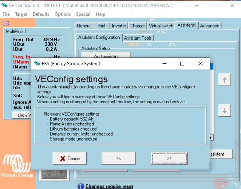
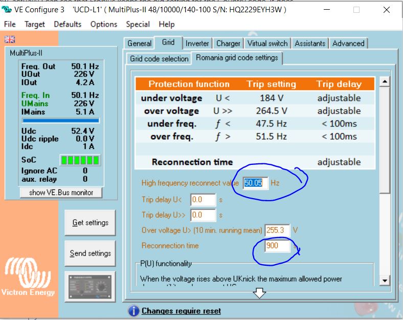
I am the new owner of 3 Victron MP 2 10000/48. I also have one Fronius Symo PV inverter 10KW and 8 Pylontech US3000C batteries. I made the installation and updated the firmware version to the latest one (506). Everything went well, so no issues. I setup the system for 3-phase configuration and sent the configuration to the devices. What I want to achieve is to use the Fronius PV inverter on the MPs output and use the solar power to charge the batteries, for house consumption and the production excess to be exported to the grid. I am located in Romania and I already export energy from the Fronius inverter to the grid. I chose the grid code to be Romania because otherwise I cannot load the ESS assistant and configured the parameters as in the attached files. I saved the configuration to be loaded on the MPs for phase L2 and L3, sent the configuration to MP on phase L1. First issue I encountered was that I cannot load the configuration saved for L1 when trying to configure MPs for L2 and L3. There is a requirement for the grid password. I do not have it, but I tried to configured everything manually and use the same parameters as for phase L1. I noticed that for phases L2 and L3 when loading the ESS assistant it does not ask you for the PV inverter power (it is only asked for L1). Ok, I loaded and wrote the config for the MPs for L2 and L3 and after doing this the inverters do not switch on and send voltage on the outputs. The following LEDs configuration appears: for L1 only the Low Battery LED is on (even if the batteries are fully charged), the rest of the LEDs are OFF, for L2 and L3 the Bulk LEDs are flashing, the rest are OFF. As a remark, the Fronius PV inverter is not yet connected to the MPs output. The Cerbo GX is not yet commissioned/setup and the batteries are not communicating with the MPs via the Cerbo GX device. Can anyone tell me what I am doing wrong?

Thank you in advance. All the best.
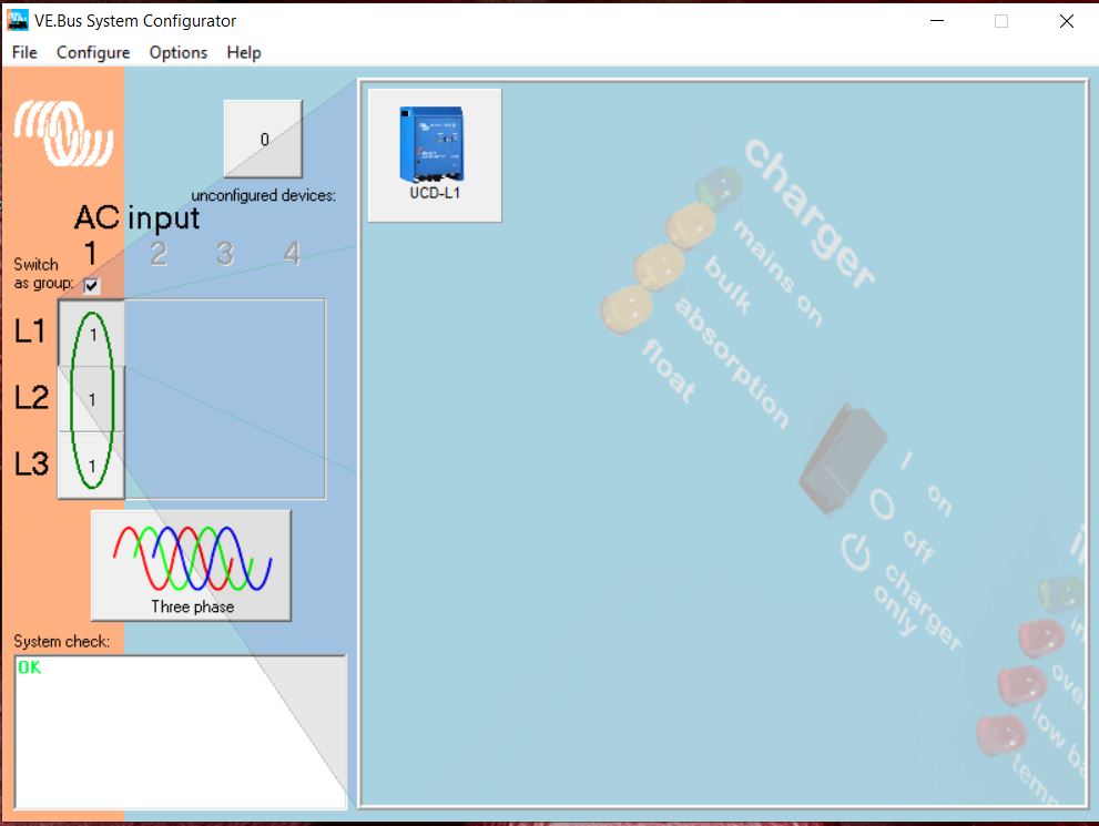
 mp2-3-phase.jpgphase-l1-charger-tab.jpgphase-l1-general-tab.jpgphase-l1-grid-tab.jpgphase-l1-virtual-switch-tab.jpgphase-l1-inverter-tab.jpgess-assistant-battery-capacity.jpgess-assistant-battery-system.jpgess-assistant-dynamic-cut-off.jpgess-assistant-frequencies.jpgess-assistant-pv-inverters.jpgess-assistant-restart-offset.jpgess-assistant-sustain-voltage.jpgess-assistant-total-solar-power.jpgess-assistant-veconfig-settings.jpg

ess settings
2 |3000

Up to 8 attachments (including images) can be used with a maximum of 190.8 MiB each and 286.6 MiB total.

2 Answers
Alexandra avatar image
Alexandra answered ·

If you dont have a grid code you cant load ESS.

First time set up allows the selection, you should not need to change it after that.

Did you buy them second hand to try to set up with a different code?

19 comments
2 |3000

Up to 8 attachments (including images) can be used with a maximum of 190.8 MiB each and 286.6 MiB total.

Dragos avatar image Dragos commented ·
They are brand new inverters. They came with None in the Grid Code and since I could not load the ESS assistant I chose the Romanian Grid Code. But, after saving the configuration to a file (for loading it onto the next 2 devices for phase 2 and 3) I cannot to that because the grid password is required. Anyhow, I configured manually the ESS for all 3 phases, but after sending the configuration to the devices, they stopped working. And my question was, why this behaviour?


0 Likes 0 ·
derrick thomas avatar image derrick thomas Dragos commented ·

If your system is configured for managed batteries but there is no communication from the batteries, ESS will not function. If I remember correctly it will only go into passthru, so if there is no ac input the system will shut off. The inverters need to be connected to the cerbo via ve.bus and the batteries need to be connected to the cerbo as well. You may need to restart or redetect the ve.bus from within the device menu of the cerbo.

Edit: you say the cerbo gx is not yet commissioned/setup. Can you explain? The cerbo is REQUIRED for ESS to operate.

0 Likes 0 ·
Dragos avatar image Dragos derrick thomas commented ·

Hi, Thomas. Thanks for the reply. Unfortunately I have not found anywhere the steps to follow when adding the ESS assistant. When you add the ESS assistant I learned that the GX devices must be disconnected. I guess there is also a warning on the Victron VE Bus config app that the GX devices must be disconnected. Now the Cerbo GX device is up and running, the batteries are also connected and I can also see the Fronius inverter in the VRM. But, without the ESS assistant loaded.

What is your advise? Connect the mains to the inverters, input power, disconnect the GX, run the VE Bus config and load the ESS assistant on all devices and reconnect the GX device. Should it work in this way? I will connect the Fronius PV inverter on the MPs output later on because I have to reconfigure that, too, to MG50, remove the Fronius smart meter and re-wire otnto the MPs output. Do you have any recommendations for the steps? Thanks and I appreciate your help.

0 Likes 0 ·
Alexandra avatar image Alexandra ♦ derrick thomas commented ·

Did you update all the inverter firmware?

@derrick thomas is correct, for ESS to work, the GX must be reconnected.

Update all firmware, get the core system working first (inverter battery gx etc, online and registered - no fronius yet). The GX after that will tell you wbat is happening or not happening.

Then load ESS and test, without the fornius.

Then connect the fronius, set up and test.

0 Likes 0 ·
Dragos avatar image Dragos Alexandra ♦ commented ·
Alexandra, thanks for your reply, but I wrote in the initial post. Yes, I did upgrade the firmware for all MPs to 506 and Cebo GX as well.

Ok, I will do as instructed. Thank you very much. I will come back to you with the update on the outcome. :)


0 Likes 0 ·
Dragos avatar image Dragos Alexandra ♦ commented ·
Now, the system is up and running without ESS assistant loaded. Just inverting from batteries, no loads, no mains, just the MPs, CerboGX and the Fronius (as it is configured now which is seen by the GX, and the batteries of course. I can see them all in the VRM.
0 Likes 0 ·
ponzoa avatar image ponzoa Dragos commented ·

Hi Dragos,

Pylontech settings Your battery settings are not correct for Pylontech batteries. Use this link to see the battery settings in VE Configure

The Cerbo should be disconnected while using VEConfigure and the MK3 device. Once configured, you should connect the Cerbo and configure the settings in that, including the ESS settings etc.

I suggest you contact your distributor from where you purchased the Multi's to help you set the Grid Codes correctly. You'll need the country code for ESS to work correctly.

Good luck!
Andrew

0 Likes 0 ·
Dragos avatar image Dragos ponzoa commented ·
Hi, Andrew. Thanks for the tips. I have not configured anything on the Pylontech side, just left the default values, but I will follow your link to see what needs to be changed. The Grid Code should be for Romania, I guess, but anyway I have the password which is required to change the grid code. I have not tested it (the password), but I hope it works. It was given by the distributor, just yesterday. Thanks again.
1 Like 1 ·
ponzoa avatar image ponzoa Dragos commented ·
Nothing to configure on the batteries. Leave them as default but be sure to change the battery settings in VE Configure to Pylontech values. Most important for me is the dynamic cut off which should all be set to 46.
0 Likes 0 ·
Dragos avatar image Dragos ponzoa commented ·

Ok, thanks a lot, Andrew. All the best.

0 Likes 0 ·
Dragos avatar image Dragos ponzoa commented ·
Dear Andrew,

it is difficult with all these devices. I setup the grid code to Romanian grid and adjust the frequency from 50.05Hz to 50.45Hz (max is 50.5Hz). Now, I setup the Fronius Symo inverter to MG50 and ESS with PV on the MPs output. Whenever the Fronius PV inverter starts to produce energy from the solar panels the MPs go to Inverter mode and Fronius restarts. It gets me crazy because actually the MPs get disconnected from the grid, but why Fronius is restarting. Any idea? Thanks a lot.

0 Likes 0 ·
ponzoa avatar image ponzoa Dragos commented ·
These frequency settings contradict the Fronius frequency shift settings. Why did you change the frequency range in the grid code? I suggest you leave the Romanian grid code settings
0 Likes 0 ·
Dragos avatar image Dragos ponzoa commented ·

I only changed the parameters highlighted in the attached picture. I was instructed to do so by the inverters provider.Grid changes.JPG

0 Likes 0 ·
grid-changes.jpg (101.7 KiB)
Dragos avatar image Dragos ponzoa commented ·
I set the value to 50.45 Hz (max allowed is 50.5 Hz) and reconnect time to 30s.
0 Likes 0 ·
Dragos avatar image Dragos ponzoa commented ·
Andrew, actually I can see that Fronius keeps the old setting for the Country code. It does not change to MG50 and I do not know why. Maybe this is the reason of this MPs behavior.
0 Likes 0 ·
ponzoa avatar image ponzoa Dragos commented ·
You need the Fronius password to change the grid code in the Fronius to MG50. This is requiered for it to accept frequency shifting. Also ensure you have Modbus TCP active in the Fronius for it to communciate via the network with teh Cerbo.
0 Likes 0 ·
Dragos avatar image Dragos ponzoa commented ·
Andrew, there is no password, just the Code for entering the Country code which is available on the internet: 73778. I chose from the list MG50, but in the end it does not change. And there is no other password requested anywhere.
0 Likes 0 ·
Dragos avatar image Dragos ponzoa commented ·
Modbus TCP is active, smart meter disabled and disconnected from the scheme
0 Likes 0 ·
Dragos avatar image Dragos ponzoa commented ·
Another strange behavior that I noticed is that when the battery bank reaches the SOC setpoint and grid is available it tries to take all the power from the grid (to not discharge the batteries further) and when this happens the MPs switch to inverter mode. There is something they do not like. The grid is disconnected. I starting to lose my mind and I might revert back to the old installation when it really worked. No ESS, just house backup and PV inverter as it was.
0 Likes 0 ·
Matthias Lange - DE avatar image
Matthias Lange - DE answered ·

Recommended settings and more for Victron + Pylontech:

https://www.victronenergy.com/live/battery_compatibility:pylontech_phantom

1 comment
2 |3000

Up to 8 attachments (including images) can be used with a maximum of 190.8 MiB each and 286.6 MiB total.

ponzoa avatar image ponzoa commented ·
connected to his system and sorted it out. All good now. Thanks.
0 Likes 0 ·

Related Resources

Additional resources still need to be added for this topic