question

trevor4321 avatar image
trevor4321 asked

MultiPlus GX2 in PassThru

This is following on from my problem with the inverter being in "sustain", voltages were set too high in the ESS Asistant for the batteries.

It's a very simple system, a MultiPlus-II 48/5000/70-50 with 3 Pylontech US2000C batteries and a analogue current transformer to monitor grid current.

Now the inverter has gone into "PassThru".

I hav checked the FAQ in "ESS Design and Install", 10.4, but all seems to be OK.

1691141522491.png

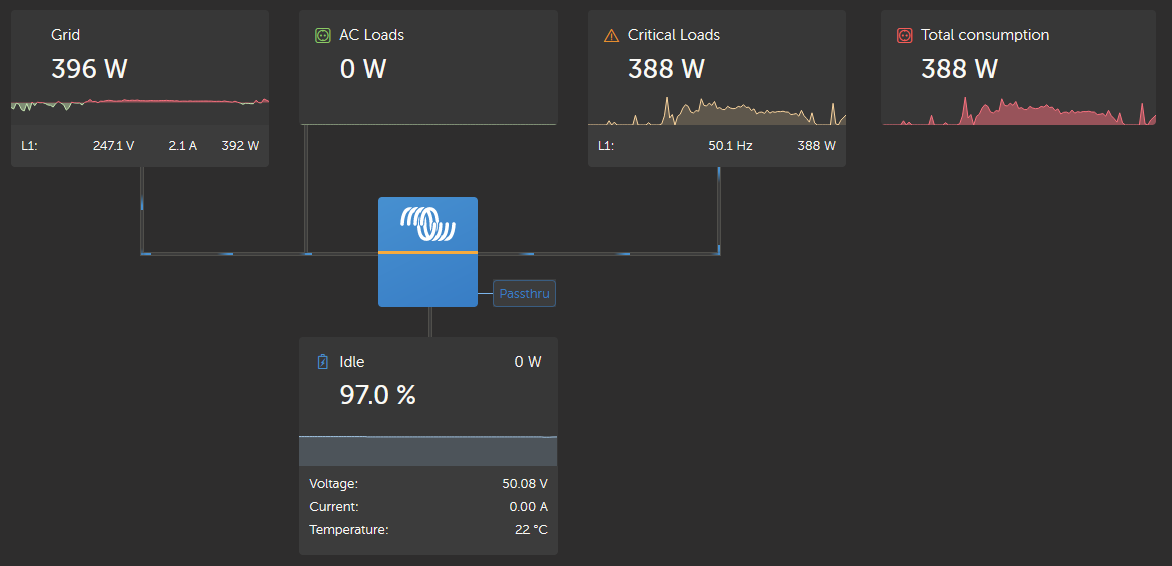
So this is showing I have both grid and battery monitoring.

1691141597937.png

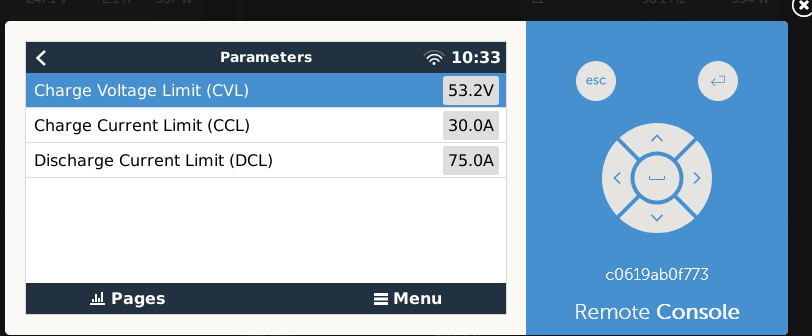
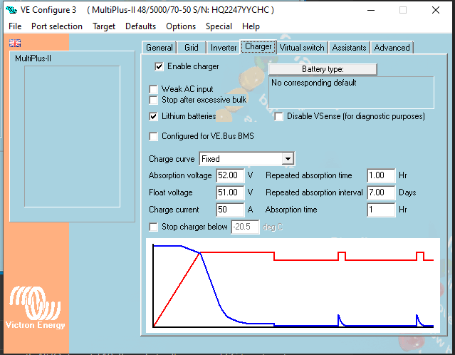
Charge and discharge are not set to 0, zero.

1691141676670.png

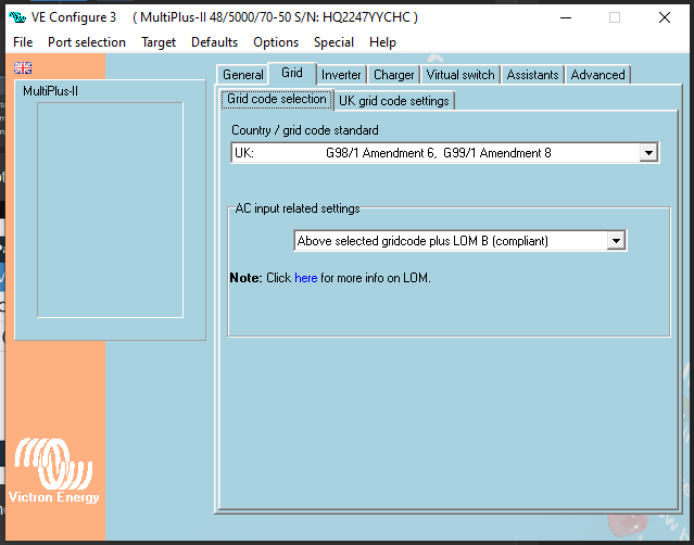
Grid code set as appropriate.

When it was in sustain the charger would come on when it was bright enough until the Pylontech BMS said no more, but it doesn't do that any more so gradually losing charge.

Thanks for any help.

Trevor


ess settings
1691141522491.png (55.2 KiB)
1691141597937.png (37.5 KiB)
1691141676670.png (32.2 KiB)
2 |3000

Up to 8 attachments (including images) can be used with a maximum of 190.8 MiB each and 286.6 MiB total.

3 Answers
Alexandra avatar image
Alexandra answered ·

@Trevor4321

I dont see solar, so i would expect a passthrough condition.

What is your State of charge in case of grid faliure? I assume you want to discharge? If you do - set that lower.

Also 50v at 97% is not exactly correct.

Have you set up everything according to the victron pylon guide?

1 comment
2 |3000

Up to 8 attachments (including images) can be used with a maximum of 190.8 MiB each and 286.6 MiB total.

trevor4321 avatar image trevor4321 commented ·

The system is an AC coupled stand alone system so solar panels not directly connected. With the state on charge in the battery it should have been inverting.

As for battery voltage/SOC voltage may be higher because the batteries had been on charge when I updated the software and before it was reconfigured back to ESS. I presume this is something coming from the BMS in the batteries, until I get it cycling properly I can then track how it's working.

As far as SOC and grid failure goes I haven't touched these at the moment, the risk of grid failure is very low and there is nothing connected to AC outs at the moment. Again, once it's running I will take it down.

I have checked the charger and inverter settings and they are to the setuo recommended for Pylontech batteries.

1691169008738.png

1691169041671.png

Thanks

Trevor

0 Likes 0 ·
1691169008738.png (57.1 KiB)
1691169041671.png (41.6 KiB)
trevor4321 avatar image
trevor4321 answered ·

I have resolved the problem.

It came down to the grid metering. The ESS Design and Installation Manual says

1691337741255.png

I am using a Victron grid meter, analogue, part no. CTR11xxxx so I set for external grid metering.

This seem to be wrong because I turned it off and it all started working.

I think this may refer to digital networked or communicated over a bus rather than just external.

But if that was the case and the MP2 was using the wrong grid meter:-

1. Why didn't I get an error because the device wasn't there.

2. How was I getting information about the power getting drawn from the grid both on the VRM dashboard and on the LCD display.

I hope this helps someone else, and thanks to all who have helped me.

Trevor


1691337741255.png (8.2 KiB)
2 |3000

Up to 8 attachments (including images) can be used with a maximum of 190.8 MiB each and 286.6 MiB total.

mjs500 avatar image
mjs500 answered ·

CTR11 is CT remote current sensor not grid meter, MP2 has CT built in on the live of AC-in

i may be wrong but even if you use CTR11 is CT remote current sensor you set it to internal in the soft ware and my mp2 setup paper work show that need to remover wire bridge INT and com and connect the red sensor wire to Ext connect the white sensor wire to com terminal ( you may have jack plug type ) and all so make show CT is install the right way around on Live wire for current flow i.e. arrow away from grid supply

with Ess software run in remote console in Ess page grid metering set to inverter/charger not external meter

ve configure general settings page 4. External Current Sensor - This is for use with the Multiplus-II external current sensor.

2 |3000

Up to 8 attachments (including images) can be used with a maximum of 190.8 MiB each and 286.6 MiB total.

Related Resources

Additional resources still need to be added for this topic