question

niteman131 avatar image
niteman131 asked

Is there a "Low Side MOSFET Switch" version of the Battery Protect ?

Hi All !

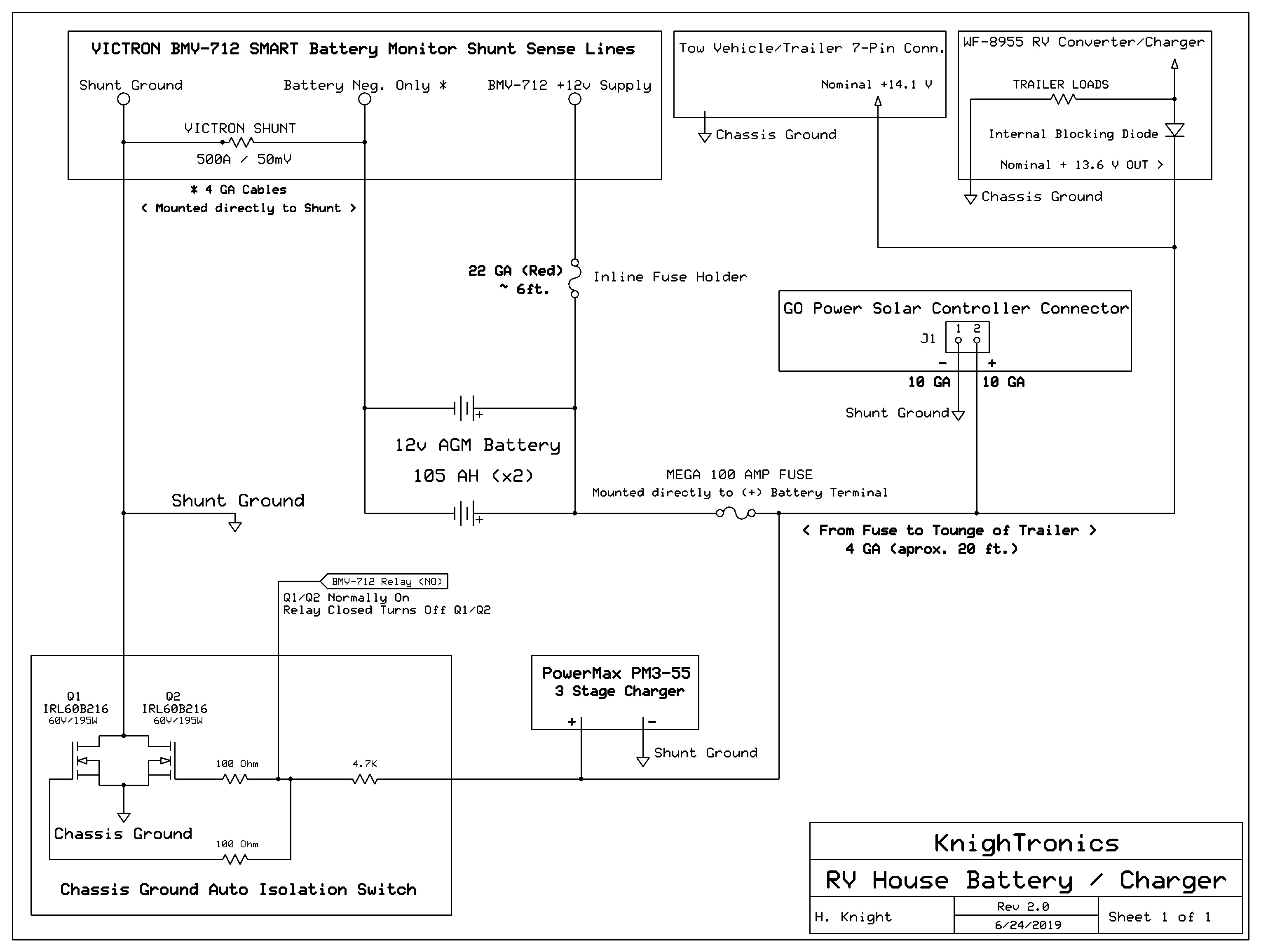
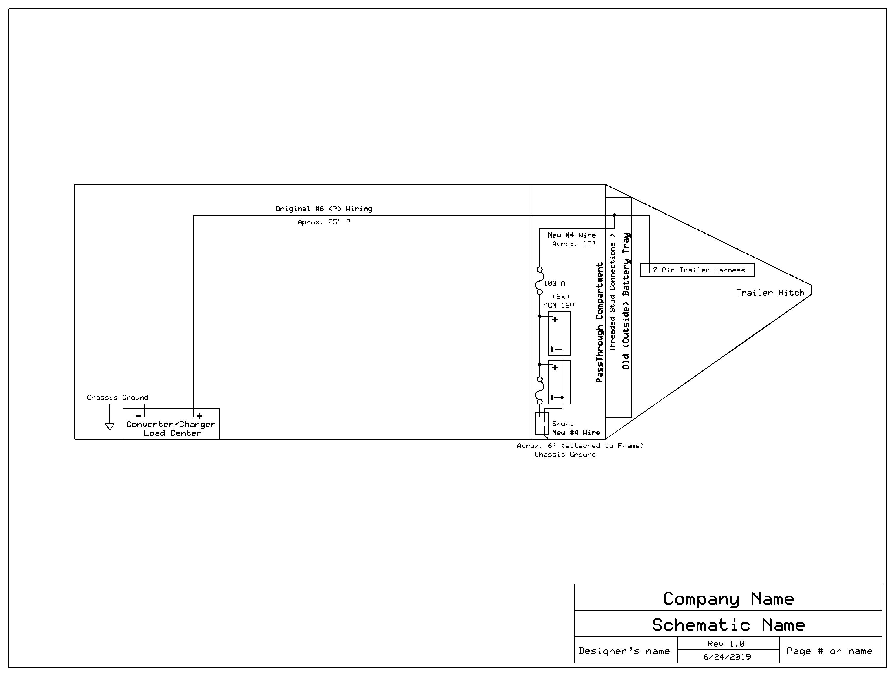
We are using a BMV-712 in an RV, and we were planning to add a Battery Protect (BP-220). However, the loads and Converter / Charger output are all wired together at the far end of the trailer, and the batteries are in the front passthrough. So separating the Converter/Charger from the loads would be difficult. Since Reverse Current through the BP-220 is NOT recommended (hence the concern about separating the loads from the charging sources), the standard "high side" wiring would be a problem.

Is there a product that could be used as a "low side mosfet switch", to be placed between the BMV shunt and RV chassis ground as a battery disconnect ? I think that the BP-220 could work, EXCEPT for the fact that the BP internal circuits need power from the "Battery" or "In" terminal on the BP.

A Battery Protect device that could get it's internal "housekeeping voltage" from a separate (low current) connection to the battery would seem to be a desirable feature so that the BP could be used as a "low side mosfet switch".

Is anyone aware of such a device ? I'm sure something could be designed to be controlled by the relay in the BMV-712 to disconnect the shunt from chassis ground at the "low voltage" alarm trip point.

Any thoughts or suggestions would be appreciated !

Battery Protect
5 comments
2 |3000

Up to 8 attachments (including images) can be used with a maximum of 190.8 MiB each and 286.6 MiB total.

niteman131 avatar image niteman131 commented ·

@Stuart

Thank you for your thoughts and suggestions. You obviously gave it a great deal of thought, and I really appreciate the time and effort you spent on your answer !

Just to be clear on my main goal: Automatically disconnect as many loads as possible before the battery bank discharges too low (below the low voltage or SOC threshold set in the BMV-712, not too worried about overcharging).

Unfortunately, my RV trailer wiring is poorly designed (skimpy wires and VERY poor layout for the shortest possible runs). If the Converter/Charger was near the front of the trailer (where the batteries are located), I would consider re-wiring things correctly, but they are at the extreme opposite ends of the trailer, which would make it VERY difficult.

I initially considered using a relay or solenoid (controlled by the BMV-712 relay), but the current to keep the solenoid/relay coil energized while the battery is "healthy" would in itself be a fairly significant drain on the battery (especially at night, when there is no Solar Power, or no Shore Power available). I do want to thank you for the suggestion about adding a diode across the relay coil....(yes, inductive EMF spikes can do nasty things).

I have given up on the idea of trying to use or modify the Victron Battery Protect devices due to my incompatible RV trailer wiring, as it would be VERY difficult to separate the loads from the charging sources, and it would probably be an expensive mistake to cut up a BP-XXX in hopes of modifying it to do what I want.

As far as I can tell, all of the loads in the trailer return to the system through Chassis Ground, so I think the simplest way to "shed the loads" when the battery reaches the low threshold set in the BMV-712 (either Voltage or State of Charge) is to "disconnect" the Victron Shunt from Chassis Ground, while keeping my charging sources connected through a "floating ground" that is hardwired to the Victron Shunt. That way, I should always have the ability to recharge the battery, and the the BMV-712 should remain functional for Voltage as well as Charging Current. I have a preliminary design that might work (looks good on paper). Although I would much rather just buy something that does what I want, there doesn't seem to be anything out there ?

I drew out a schematic of my system. The proposed "future circuitry" is show in the bottom 1/3 of the drawing ("Chassis Ground Isolation MOSFET Switch" and an "Upgrade" 3 Stage Charger that I bought but never installed because it would not fit in the existing "RV Power Panel"). I am new to the Victron Community format, so I am not sure if my attachment will work ?


In any case, I would like to thank you again for taking the time to analyze my situation and present some potential solutions !!

0 Likes 0 ·
niteman131 avatar image niteman131 commented ·

@Stuart

The .jpg of my schematic did not show up in my previous comments, so I'll try again....

0 Likes 0 ·
1561368452797.jpeg (645.8 KiB)
niteman131 avatar image niteman131 commented ·

@Stuart

I think I made at least one mistake in my schematic. The "Trailer Loads" should be on the Cathode side of the "Blocking Diode" (not the Anode side) in the Converter/Charger block.

I was told about the blocking diode by Technical Support at WFCO (the Converter/Charger manufacturer), but since I don't have a schematic of their unit, I can't be sure. But if the loads were on the Anode side, I don't think I would be having a problem with discharging the battery :)


0 Likes 0 ·
Stuart avatar image Stuart niteman131 commented ·

Hmmm.

I see your problem. Not the best manufacturer installed layout I have seen that's for sure.

I can fully understand your reluctance to start cutting looms in the existing wiring harness. Can you confirm for me the cables that go to the battery, there looks to be two of them and another idea I had will only work if that was the case.


I like the design of the ground isolation to prevent load discharge. Just to clarify the relay I was referring to that would perform load isolation is more of a contactor that has a motorised cam that makes and breaks the circuit. This would not be a vampire load as the limit switch would isolate the motor at the end of its travel.


The issue I can foresee with the ground isolation is that there may be concealed grounding points that you are not aware of and you may end up with the equivalent of a floating neutral in mains terms. This could create all kinds of problems and current leakage on your system.


Something that came to mind this morning was a forward diode inline with a relay. The battery protect would be connected in the normal way but if the second + line is present you could recharge via that path. Even if the battery protect had isolated the supply from the battery any current flowing towards the battery would pass via the diode, close the relay and connect that cable directly to battery + and allow the charger access to the battery.


If that second cable is not present then I have another idea that may work. As the battery protect is inline with the + from the battery and uses one of the post terminations to make the voltage measurement and you want to isolate the ground return you may open a can of worms.


Can you confirm the cables to the battery and if possible take a picture? I have an alternative idea that may work for you. If you can come back to me on that wiring we can progress from there.


Many thanks.


Stuart

0 Likes 0 ·
niteman131 avatar image niteman131 Stuart commented ·

@Stuart

Thanks again for your suggestions. I was not aware of an Actuator with "limiting gears". Please send a link if possible as that might be a better, simpler solution.

My son is on his "Maiden Voyage" (first RV excursion, half way across the country), so I wont be able to take any pictures or do any work on the RV until he gets back, but I do want to have some solution(s) ready to help prevent his batteries from experiencing an untimely death !

I drew out a more physical layout of the RV Trailer wiring (see below). Hopefully that will give you a better idea of the actual wiring. Basically, we got rid of the old dead battery that was outside on the front of the trailer, and put the new AGM batteries, Victron Shunt, and BMV-712 in the PassThrough compartment.


I've got to run, but I really do appreciate your suggestions, and the interest you've taken in helping me solve this puzzle.

Thanks, Howard

0 Likes 0 ·
1561414693745.jpeg (356.8 KiB)
1 Answer
Stuart avatar image
Stuart answered ·

@Niteman131

Hello.

The components in the battery protect are going to include a "P" channel mosfet. That would have to be changed to a "N" channel type and Victron would have to effectively double production by making two versions of each product.


The first solution that comes to mind is to run a small gauge cable to the positive out on the battery protect and the other side to the battery positive. Run the small cable to your main junction box and at that point connect a high current relay to separate your loads using the relay to do so..... Or


Install the battery protect at your main junction box between the supply from the battery cable coming in and your loads. You would see a voltage drop but could compensate for this by lowering the cut off voltage by 0.5V of whatever your voltage drop may be.


The second solution would allow you to see the current draw but the first one would not. As you mentioned above you could use the BMV-712 relay output to a high current relay. If you do use a relay I would advise connecting a diode across the relay coil to protect your devices from high voltage spikes when the large relay de-energises ! I would program the relay on the BMV-712 to switch at 50% state of charge instead of by voltage.


Without running another cable there is only one other way I can think of but without seeing the circuit diagram of the battery protect I do not know if this will work. It may cause damage to the battery protect so its at your own risk........

The idea would be to use a large high current schottky diode across the battery + and load bolts. You would have the diode oriented so it would allow current flow towards the battery only. Any current being drawn from the battery would stop at the diode and have to use the battery protect to supply any loads. When being charged the current would bypass the battery protect and use the diode to charge. Again I am not sure how well this would work if at all and would mean your warranty would be void.


If it was my system I would do one of two things.

1. If possible disable the charger in the converter (there may be a seperate fuse) and wire the battery connect as normal. You could do this if a site / shore mains supply was nearby and connect one of the high power victron battery chargers direct the the positive battery terminal leaving the cable going back to the charger/inverter unit as a load only cable. The victron chargers have bluetooth status and control and give out a very clean supply. The victron chargers also have propper multi stage charging so would keep your battery healthier.

2. Bite the bullet and if it is possible run a large gauge cable from the charger module direct to the battery + terminal. From the way you describe your setup I don't know if you could do this.


I hope this is of help to you or at the very least give you some idea's as to how to get around the problem. If you have any questions please post back.


Stuart

2 |3000

Up to 8 attachments (including images) can be used with a maximum of 190.8 MiB each and 286.6 MiB total.