question

bazil avatar image
bazil asked

Using BMV-712 Smart relay to control Multiplus 12/1600/70-16 (switch to inverter or AC )

Could anyone please help me with configuring the following:

The goal is to use Multiplus 12/1600/70-16 on inverter until the battery has sufficiently depleted and to then activate AC input and charger.

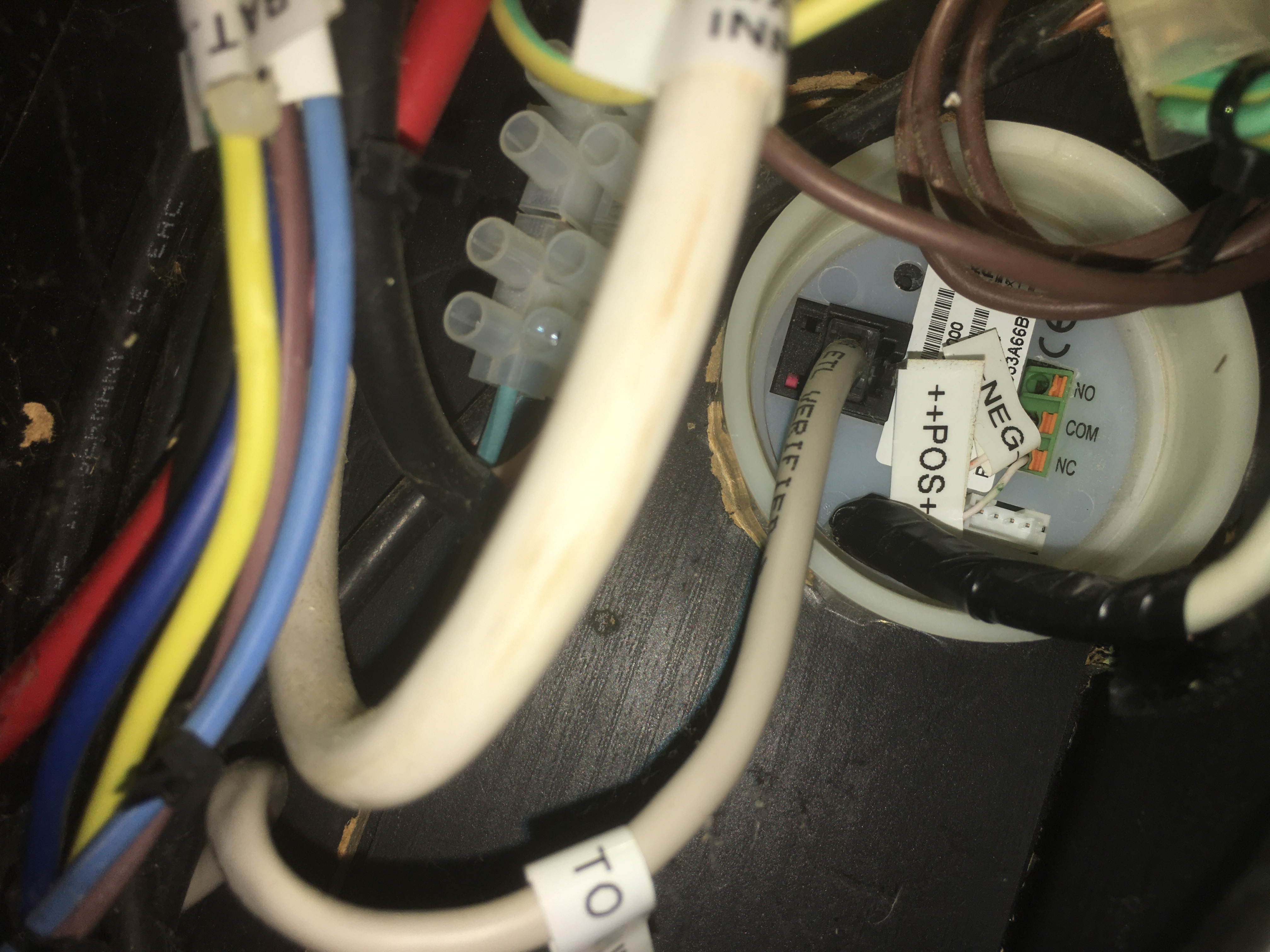
I have a BMV-712 with Smart shunt mentor.

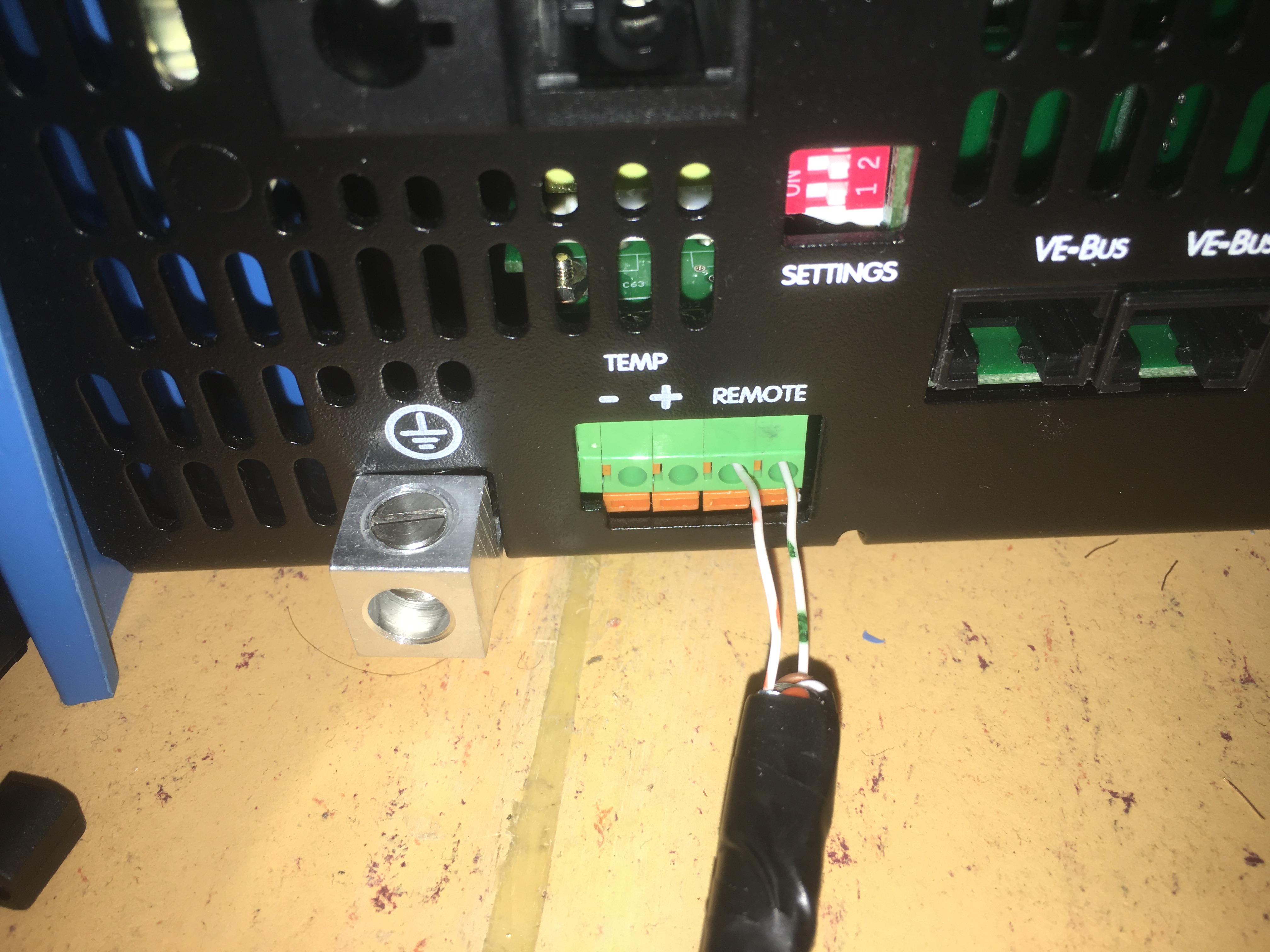
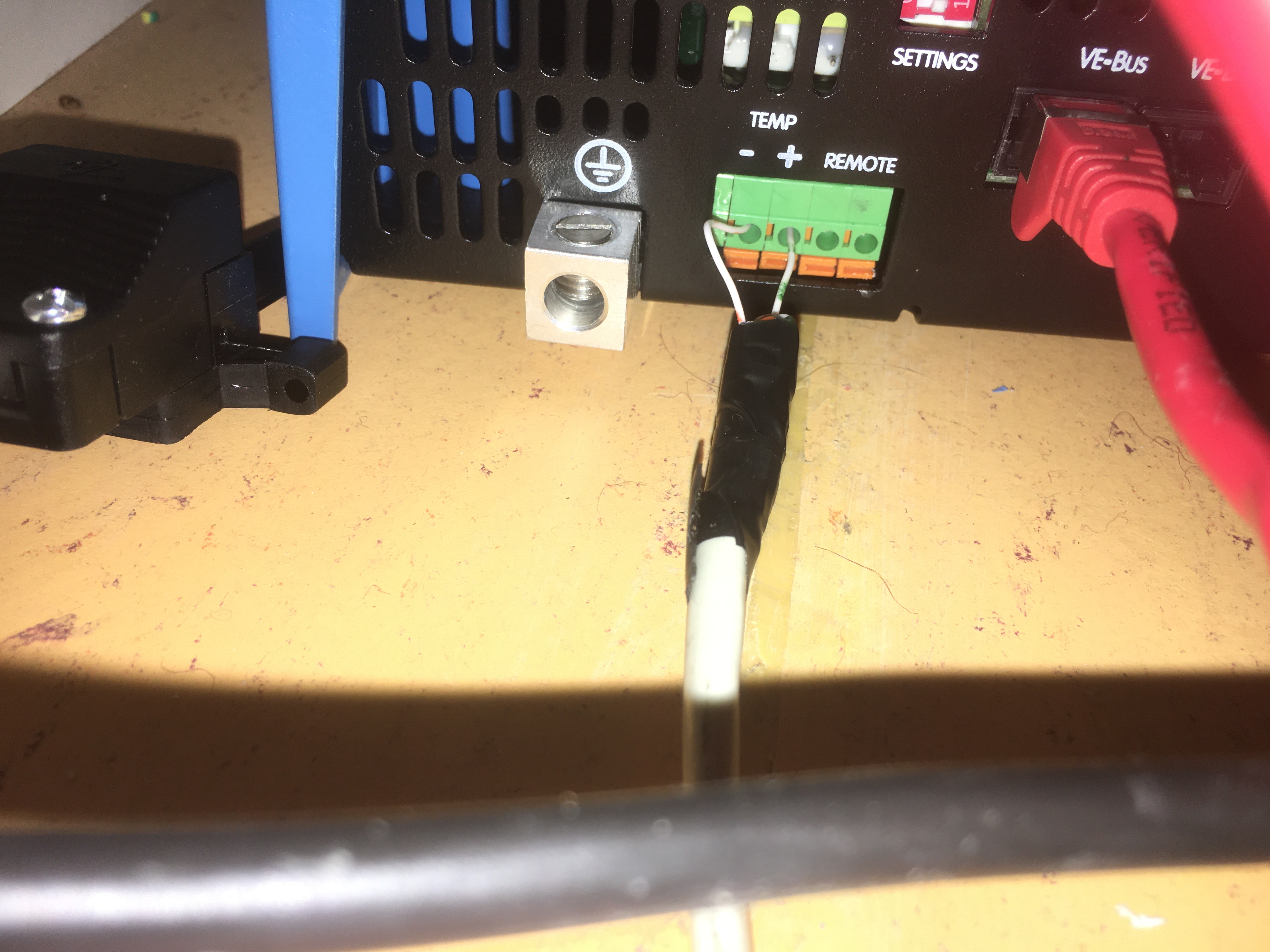
Can I use the relay function on the BMV to switch the Multiplus from inverter to AC?

The Multiplus 12/1600/70-16 has two ethernet VE Bus ports; do they do exactly the same thing?

Best regards
Stephen

BMV Battery Monitormultiplus ve.bus
2 |3000

Up to 8 attachments (including images) can be used with a maximum of 190.8 MiB each and 286.6 MiB total.

8 Answers
Alexandra avatar image
Alexandra answered ·

@Bazil

Are you using a GX at all?

If not the easiest is to use the relay to switch a contactor to disconnect and reconnect the mains.

The two VE bus ports are the same. There are two so that comms between multiple units is possible such as in a three phase system. And the other use the VE bus bms for use with victron batteries.

2 |3000

Up to 8 attachments (including images) can be used with a maximum of 190.8 MiB each and 286.6 MiB total.

bazil avatar image
bazil answered ·

@Alexandra

Many thanks for your help; could you please suggest which GX device(s) I would need in order to achieve my goal?

Best regards

2 |3000

Up to 8 attachments (including images) can be used with a maximum of 190.8 MiB each and 286.6 MiB total.

mondeoman avatar image
mondeoman answered ·

Yes, you can use the BMV relay to control the AC Input of the MultiPlus.

Connect the relay to the Aux (or Temperature Sense) input of the inverter.

Install 3 assistants, as shown in the attached picture.

The picture refers to "Auxiliary Input 1", but you can also use the Temp. Sense input.

general-flag.png


general-flag.png (58.5 KiB)
2 |3000

Up to 8 attachments (including images) can be used with a maximum of 190.8 MiB each and 286.6 MiB total.

bazil avatar image
bazil answered ·

@MondeoMan

Thank you so much for your help; I followed your instructions implicitly namely successfully constructing and transferring the assistants.

I connected the BMV to the remote terminals on the inverter. The BMV relay shut the inverter down, but unfortunately AC from the mains did not activate, so basically the unit turned itself off.

Any idea what I might have overlooked; I tried using the temperature input, however it didn’t react at all.

Attached some images.

f15fb254-08ad-41bf-adaa-d4301a90bbe4.jpeg

7e911454-9619-4bdf-b898-7499c91536d7.jpeg

1d371534-d30e-449f-bb1a-05f251ed028d.jpeg


2 |3000

Up to 8 attachments (including images) can be used with a maximum of 190.8 MiB each and 286.6 MiB total.

mondeoman avatar image
mondeoman answered ·

@Bazil Clearly you do not want to use the REMOTE input, that just shuts down the inverter.

Let's take it step by step.

Step 1: You should re-configure the assistants accordingly to use the TEMP SENSE input. Show us a screenshot of your Assistants Summary. Then you can experiment with a simple wire bridge between the two TEMP SENSE input pins.

When this works, we can move on to step 2, the connection of the BMV relay.

2 |3000

Up to 8 attachments (including images) can be used with a maximum of 190.8 MiB each and 286.6 MiB total.

bazil avatar image
bazil answered ·

@MondeoMan

Many thanks! Herewith are my settings.

- should I now place a wire bridge between the minus/plus inlets of the temperature sense input?
- should I remove the current wire bridge located in the remote inlets?

summary2.jpg

summary.jpg


summary2.jpg (46.5 KiB)
summary.jpg (135.3 KiB)
2 |3000

Up to 8 attachments (including images) can be used with a maximum of 190.8 MiB each and 286.6 MiB total.

mondeoman avatar image
mondeoman answered ·

Do not use the REMOTE input. Leave it exactly as it was before you touched it. There should be a small black wire bridge in there, put it back as it was.

Use a second wire bridge that you repeatedly insert and remove in the TEMP SENSE inputs to confirm that the assistants work as expected. Make sure to strip the ends of the wires about 1 cm before inserting.

2 |3000

Up to 8 attachments (including images) can be used with a maximum of 190.8 MiB each and 286.6 MiB total.

bazil avatar image
bazil answered ·

S

@MondeoMan

Success!

The Remote is bridged and the BMV relay is wired into the -/+ ports of the temperature sensor.

The open/close relay behaviour of the BMV results in the Multiplus correspondingly switching from inverting to AC input and vice versa.

This is an excellent solution! Thank you so much; it works like a charm!

2 |3000

Up to 8 attachments (including images) can be used with a maximum of 190.8 MiB each and 286.6 MiB total.

Related Resources

Victron BMV battery monitors product page

Additional resources still need to be added for this topic