question

a-team-adventures avatar image
a-team-adventures asked

Temperature sensor DIY?


Hi guys

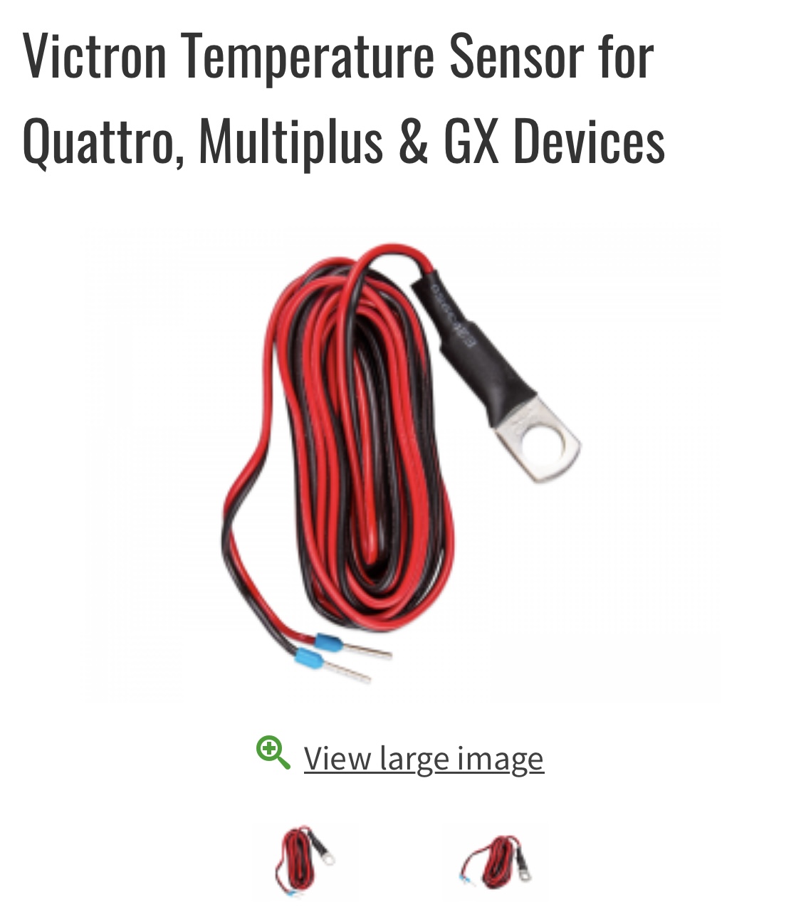
Tried to get one of these before our big trip but no luck. So I’m thinking of making one.

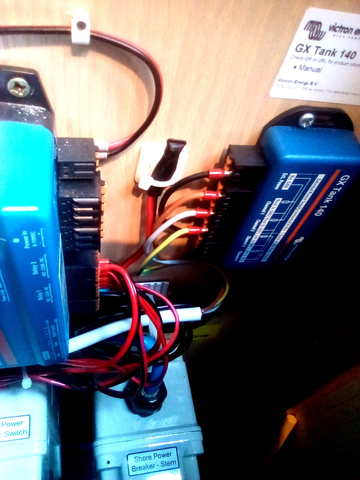
I have some 1mm2 wire, and can crimp to fit inside the Cerbo connector box… guess the other ends just go onto a large lug?

I know I’m being fairly simple but anyone know if it’s more complicated than that? It’s an analogue input to the Cerbo; I’ve already connected my water tanks, all good just don’t want to damage anything?

Alex


8dda2326-03be-4aef-afb8-3bca5f97af46.jpeg


Temperature Sensor
2 |3000

Up to 8 attachments (including images) can be used with a maximum of 190.8 MiB each and 286.6 MiB total.

5 Answers
pwfarnell avatar image
pwfarnell answered ·

The device is an LM335, connect the +ve and -ve wires to the correct terminals on the device, do not connect anything to the third adjustment terminal and it will work. I have 3 home brewed ones on my Cerbo GX.

3 comments
2 |3000

Up to 8 attachments (including images) can be used with a maximum of 190.8 MiB each and 286.6 MiB total.

pwfarnell avatar image pwfarnell commented ·
Search on this forum for LM335 and see several posts.
0 Likes 0 ·
a-team-adventures avatar image a-team-adventures commented ·
Hi could you send me the recipe for your home brewed ones - I've about 4 days to knock something up. I'm on whatsapp +968 71963525
0 Likes 0 ·
pwfarnell avatar image pwfarnell a-team-adventures commented ·

I bought LM335. As per drawing on datasheet linked below and sketch copied from it I cut off the ADJ pin, shortened the other 2 pins to about 8mm. I then soldered on a twin core red/black wire, red to + and black to minus. Small diameter heatshrink was added over the solder joint and pins to prevent them shorting out (this needs putting on the wire before soldering. I then put a larger piece of 8mm dia heat shring over the whole lot. I crimped 1mm2 or 1.5mm2 bootlace ferrules onto the other ends of the wire and inserted these into the Cerbo GX. Picture of one in the electrical locker clipped to a cable tidy.p


screenshot-20230618-114217.png

0 Likes 0 ·
sharpener avatar image
sharpener answered ·

I think you will find under the sleeving is a thermistor (or possibly a thermocouple) which is the component which actually measures the temperature, the lug is just to make good thermal contact.

2 |3000

Up to 8 attachments (including images) can be used with a maximum of 190.8 MiB each and 286.6 MiB total.

sharpener avatar image
sharpener answered ·

and here is the data sheet.

2 |3000

Up to 8 attachments (including images) can be used with a maximum of 190.8 MiB each and 286.6 MiB total.

a-team-adventures avatar image
a-team-adventures answered ·

I found a thermo couple in Riyadh.. I’ve connected it to the Cerbo and activated the ports. It’s working but reads 125 degree Celsius… it’s hot outside (currently 50) and inside the boot is 28, but seems to be no way of calibrating the temperature sensor I bought

1 comment
2 |3000

Up to 8 attachments (including images) can be used with a maximum of 190.8 MiB each and 286.6 MiB total.

sean avatar image sean commented ·

A thermocouple is not the correct device, it needs to be an LM335.

2 Likes 2 ·
phaser avatar image
phaser answered ·

Do I need to solder "plus" also to ring eyelet?

Actually I've done it exactly the way like described here. However, the cable with sensor isn't working on my Smart Shunt 500.

What I've done differently is that after soldering and putting isolation around, I've glued it into a M8 ring eyelet. I have connected "plus" only to LM335 and not to the ring eyelet. Is that maybe the fault as there is no power getting from battery pole via ring eyelet to cable and thus Shunt?

3 comments
2 |3000

Up to 8 attachments (including images) can be used with a maximum of 190.8 MiB each and 286.6 MiB total.

pwfarnell avatar image pwfarnell commented ·

The information above is all to do with the Cerbo GX / Multiplus temperature sensor which is isolated from the terminal lug.

The temperature sensor for the SmartShunt is different to the one for the Cerbo GX / Multiplus, they are not interchangeable.

The temperature sensor for the SmartShunt has 2 functions, the terminal is connected to the positive of the battery to provide the power to the SmartShunt and also the voltage sense. It also incorporates a temperature sensor which must somehow send the temperature signal down the negative cable to the SmartShunt. I have not seen any details of what is in the sensor, no idea if it is the LM335 or not.

1 Like 1 ·
Delta Victor avatar image Delta Victor commented ·

The temperature sensor ASS000100000 for the smartshunt uses a NTC 150Kohm

See this thread

And like @pwfarnell said it's a temperature sensor and also the positive connection to the smartshunt.

0 Likes 0 ·
sv-soleil avatar image sv-soleil Delta Victor commented ·

@Delta Victor do you have personal knowledge, besides referencing @WKirby‘s answer, that this sensor uses an NTC 150? There seems to be some confusion on this. Did you by any chance look inside one?

0 Likes 0 ·

Related Resources

Victron temperature sensor disambiguation table - which product supports which sensor