question

hari-offgrid avatar image
hari-offgrid asked

Deadlock on Multiplus II GX with VRM On/Off and Safety Assistent

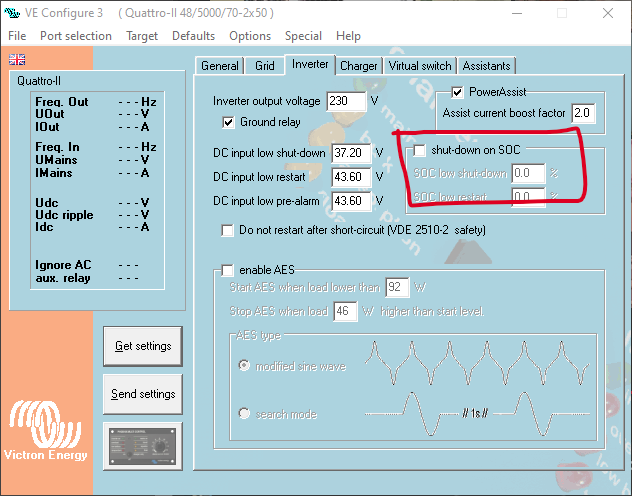
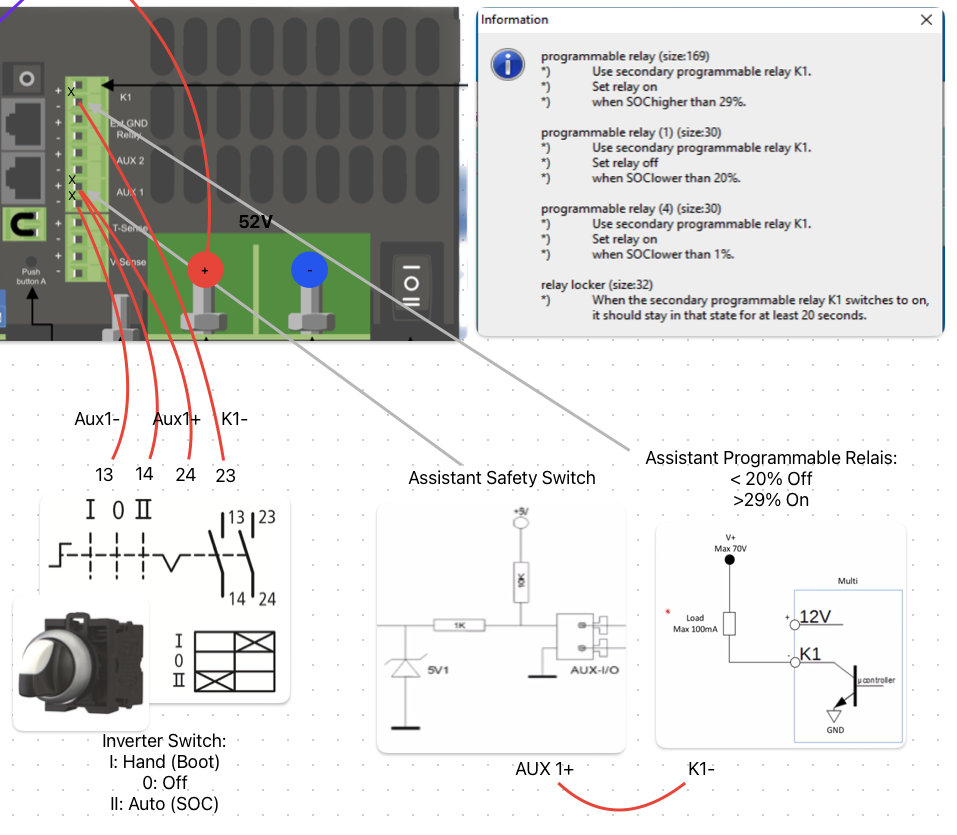
My Multiplus is running offgrid and is used to load a e-car. The inverter is switched on and off via VRM. To automatically stop the inverter I use the programmable relais K1 (<20% SOC -> Off) and connect the output to the safety Assistent at AUX1, This runs fine.

But.

To connect a Grid-Meter i bought a passive USB Hub. I plugged off my solar charger 2 from USB and plugged in the HUB. There was a „click“ and the GX device was off. This happens in state OFF of the Multiplus.

I thought Uihh... and other thoughts… broken? Defect?

I remembered the warning about a deadlock with the GX device.

1. Plugged of the GX internal from the VE Bus. Nothing changed

2. Temporarily connected the Multiplus with the grid. Nothing changed

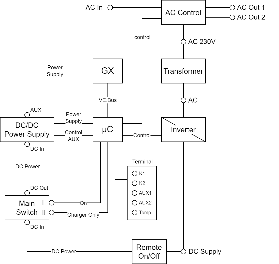
3. Opened the Remote On/Off on the Multiplus terminals. The display of the GX device was on for a second.

4. Short cut AUX1 to enable Inverter via AUX1. That was it.

My Multiplus is running again. Puhh


Some technical background would be fine. And maybe a warning in the manual of the Multiplus GX,

I opened the Multiplus for step 1, and surprise there is a additional VE Direct port (required for internal MPPT in Easy Solar devices). Is this port usable? If yes I do not need the USB Hub


Be carefully with USB Hubs.

Harald


Edit: Changed Security to Safety and solar inverter to solar charger

multplus 2 gx
2 |3000

Up to 8 attachments (including images) can be used with a maximum of 190.8 MiB each and 286.6 MiB total.

4 Answers
Matthias Lange - DE avatar image
Matthias Lange - DE answered ·

Not sure what you mean by:
"I plugged off my solar inverter 2 from USB"
What solar inverter?

Why you don't use the "shut-down on SOC" feature?

1686232893838.png


1686232893838.png (64.0 KiB)
7 comments
2 |3000

Up to 8 attachments (including images) can be used with a maximum of 190.8 MiB each and 286.6 MiB total.

hari-offgrid avatar image hari-offgrid commented ·

Sorry, I mean my second MPPT solar charger, which is plugged to USB.


As far as i remember I tried that. But it didn‘t work, As far as I remember I‘ve read somewhere, that the inverter isn’t using this rule when no grid is connected, because it does not knows if the AC devices can be switched off by the inverter. „UPS“ mode. Maybe I have to switch off the AC input via configuration?

Edit: UPS instead USV

0 Likes 0 ·
Alexandra avatar image Alexandra ♦ hari-offgrid commented ·
@Hari OffGrid

It uses the SOC feature in offgrid mode. I have several systems that do it correctly. They restart automatically at the restart percentage after solar has raised the SOC up again.

2 Likes 2 ·
hari-offgrid avatar image hari-offgrid Alexandra ♦ commented ·

@Alexandra

Thank you very much for your comment. Since a grid is not physically connected, I didn't care too much about the settings in the grid tab. But it seems that there are some hidden features in Multiplus that are not all documented. Also the fact that DCL is currently not considered could be one of them.

I assume that disabling "AC In" and UPS is the trick for the SOC function. But is there a difference internally between the safety switch assistant and the SOC feature? If not, the deadlock may also occur with the SOC feature.


0 Likes 0 ·
klim8skeptic avatar image klim8skeptic ♦ hari-offgrid commented ·

@Hari OffGrid I opened the Multiplus for step 1, and surprise there is a additional VE Direct port (required for internal MPPT in Easy Solar devices). Is this port usable? If yes I do not need the USB Hub

I believe the internal VE Direct port is usable.

1 Like 1 ·
Alexandra avatar image Alexandra ♦ klim8skeptic ♦ commented ·

Correct the ve direct is useable and is documented.

If you are not using the grid, anything on the grid tab does not related to you so that includes the ups function you refer to. No it has nothing to do with DCL

The inverter tab is whemat you need to set.

The DCL is set by your battery when it communicates with the GX so is not user settable or magically hidden.

It would not be a concern either with a correctly sized battery.

What you do need to do @Hari OffGrid is spend more time reading the documentation.

The deadlock does not occur with the SOC shutdown function, like i said i have self recovering not grid connected, unattended systems that use the feature.

1 Like 1 ·
Alexandra avatar image Alexandra ♦ Alexandra ♦ commented ·

You have overcomplicated your system and it is giving you a headache.

1 Like 1 ·
hari-offgrid avatar image hari-offgrid klim8skeptic ♦ commented ·

Thank you for this hint. I searched more about this and found:

1. It’s only 1 VE.Direct specified for Multiplus GX, see https://www.victronenergy.com/live/venus-os:start

2. But there has been other feedback on this, see

https://community.victronenergy.com/questions/147786/second-vedirect-port-on-multiplus-ii-gx.html

This as additional information from my side.

0 Likes 0 ·
hari-offgrid avatar image
hari-offgrid answered ·

Hi, I have read a lot of documentation available on the Victron product page. Unfortunately, I often had to google for specific details. Perhaps this is intentional on Victron's part to prevent users from getting headaches trying to do their own project. I may also have overlooked a document. I‘ve read the manuals for the Multiplus GX, VE-Bus, GX, VE-Config etc. The issue with the ignored DCL is my experience and as a result I‘ve tried to stop the discharge somehow.

I would try to change the grid settings to check the reactions with DCL and the SOC function. But, right now the system is running as expected and I have learned more about a potential deadlock in a „Multiplus GX“ and how to fix it :) A fix with a small wire is not the worst idea in my opinion. Do not change a running system, is my motto.

@Alexandra Thank you very much for your help and advice. I have learned more about the Multiplus during this discussion.

2 comments
2 |3000

Up to 8 attachments (including images) can be used with a maximum of 190.8 MiB each and 286.6 MiB total.

JohnC avatar image JohnC ♦ commented ·
@Hari OffGrid

Victron can't possibly document every quirk that may happen when users get 'imaginative'. Many do (me too), and and what you've done there I wouldn't have even thought of. Clever it is, but you found the downside.

For me, shutting down the inverter is a no-no. If I wanted to switch a load based on SOC (and even other stuff), I'd wire that load to the Multi's ACOut2 and switch that.

0 Likes 0 ·
Alexandra avatar image Alexandra ♦ JohnC ♦ commented ·

@Hari OffGrid

This is what i was coming back to add, to control discharge current the best way is to control load. You know how much in total you can run safely off the battery keep the load in that margin.

I have big stuff on AC2 out which can switch off above a certain load and you have SOC control which is important offgrid. I did at one point also have an extra load on a contactor (adding to AC1) signalled from the K1 relay that could switch on and off based on load.

Definitely better than switching off the whole inverter.

0 Likes 0 ·
johanlee094 avatar image
johanlee094 answered ·

Despite Victron's best efforts, it is impossible to document every quirk that might occur as a result of users being "imaginative". Many people do (I am one of them), and what you have done there I would never have even thought of doing myself. This is a clever technique, but it has a downside as well.

In my opinion, shutting down the inverter is not a good idea. For example, if I wanted to switch a load based on SOC (or even other stuff), I would wire that load to the Multi's ACOut2 and switch it from there.

2 |3000

Up to 8 attachments (including images) can be used with a maximum of 190.8 MiB each and 286.6 MiB total.

hari-offgrid avatar image
hari-offgrid answered ·

FYI (Updated, Aug 15th):


I have tried to represent my knowledge, what I have learned so far (as a user), in a logical block diagram. A diagram that I have not seen before. And this is based on my little knowledge about electronics. With this, in my opinion, I can assume:


gx.png


  1. The main switch and the "Remote On/Off" switch are the only two that turn off the internal power supply. All other switches are controlled by the µC. I call them software switches.
  2. I believe that the power supply of the GX card is controlled by the µC. The deadlock may occur when the power supply is turned on and the µC boots differently than the GX card. There may be a condition that is not triggered that keeps the GX card alive. But this is just a guess from me.
  3. Switching the inverter via VRM (and GX) on and off is a software switch.
  4. Switching the inverter via safety assistant on and off is a software switch.
  5. switching off the inverter via software switch only means that the signaling of the FET transistors is stopped. These are permanently switched on and off for inverting. It should not be a problem to switch them off permanently by switching off the inverter via software.


As a conclusion:

I see no problem with switching the inverter via software. Since I only have individual AC loads that are temporarily connected to and disconnected from the Multiplus inverter. Loads that can be switched off any time.


Improvement (Updated):

I still use the safety switch to switch my inverter on and off dependent on the SOC (Auto mode) or manual (Hand mode) via an external switch. The external switch is shown in the following image. I added an additional rule (4) to the programmable relay to switch the inverter on during boot when the SOC data is missing (= 0%?) to hopefully prevent the mentioned boot problem. If this doesn't work there is still the Hand mode.


safetyswitch.png


I love quirky solutions :)


gx.png (112.9 KiB)
safetyswitch.png (303.8 KiB)
2 |3000

Up to 8 attachments (including images) can be used with a maximum of 190.8 MiB each and 286.6 MiB total.

Related Resources

Additional resources still need to be added for this topic