question

adev avatar image
adev asked

Reconditioning victron LFP batteries, cell voltages?

I recently got a pair of Victron 60 ah NON-SMART 12.8v Lithium iron phosphate batteries on ebay. They were both received at around 13.2v which is fine, but the seller also gave me 2 more of the same spec that were each at around 9.9v.

Being the non-smart versions, I obviously can’t connect with bluetooth to see the individual cell voltage, but is there any way at all that this information can be seen? I currently have a Victron 100/20 MPPT charge controller, and will have a VE.bus BMS on order soon. Will the BMS interterface with the smart solar charger, or with any other device and pass the individual cell voltage on so I can see that?

I also have a rPi if it’s somehow possible to do with that...

I connected the two 9.9v batteries in parallel yesterday and charged them at 1A (the lowest I could set the smart solar 100/20) untll the votlage got to 11.5v this morning (it held at 10.04v overnight), where it seemed to stop, then upped it to 2ah and it’s now at 12.95v.

EDIT: It charged up gradually to 14.0v today, but it has since fallen back down to 10.73 now that no charge is coming in. I’ll se how it does overnight.


Any further thoughts welcome.

battery chargingLithium Battery
2 |3000

Up to 8 attachments (including images) can be used with a maximum of 190.8 MiB each and 286.6 MiB total.

6 Answers
Paul B avatar image
Paul B answered ·

No there is no way to monitor the cell voltages, unless you take the top off the battery, even the VE-BMS does not monitor them, it monitors 3 normaly closed loops as fare as my tests have shown, that is

there are 3 circuit loops coming out of the batteries 1 for temp one for L/V and one for H/V

And I have only determaind this by testing what a VE-BMS unit does on its 3 control signals.

if I were you I would be VERY closely monitor the H/V circuit for a open condition and then shut down charging FULLY if it goes open as one cell has a high voltage

colors are

Brown loop

Blue Loop

Black Loop


the black is for Temp and I cant remember what way around the brown and blue are.


2 comments
2 |3000

Up to 8 attachments (including images) can be used with a maximum of 190.8 MiB each and 286.6 MiB total.

adev avatar image adev commented ·

OK thanks, that’s helpful and a bit disappointing but actually more or less what I thought.

0 Likes 0 ·
adev avatar image adev adev commented ·

there are only two wires coming off the BMS to the (CANBUS?) connectors: red and black.

0 Likes 0 ·
adev avatar image
adev answered ·

Well it didn’t hold charge: the voltage quickly fell down to around 10.6v after I stopped charging, and held there. I noticed the top cover on one of the batteries was a bit loose so I took it apart - there was acually quite a lof ot liquid in there, presumably water (although it smelt quite strongly of solvent but I guess that was the glue holding the casing together) - no idea how it got in there but before I got hold of them.

One of the cells was totally flat - 04mv, the other three seem very happy at around 3.5v.

I will take the other battery apart as well and I expect I’ll fund the same thing in there. Hopefully I can make one good battery out of the two.

3 comments
2 |3000

Up to 8 attachments (including images) can be used with a maximum of 190.8 MiB each and 286.6 MiB total.

nebulight avatar image nebulight commented ·

Post pictures! I've always wanted to see the inside of a victron battery.

0 Likes 0 ·
adev avatar image adev nebulight commented ·

Here you go... :)

0 Likes 0 ·
nebulight avatar image nebulight adev commented ·

Very interesting, thanks for posting. It looks to be passive balancing as it looks to have 3 resistors per cell on the BMS board. This is probably why they suggested such a long absorption time so the pack could balance. I've always been curious as to why have such a long absorption time. Looks like the smart battery have more than just bluetooth as an upgrade as they now have active balancing as well.

Thanks again for posting.

0 Likes 0 ·
adev avatar image
adev answered ·

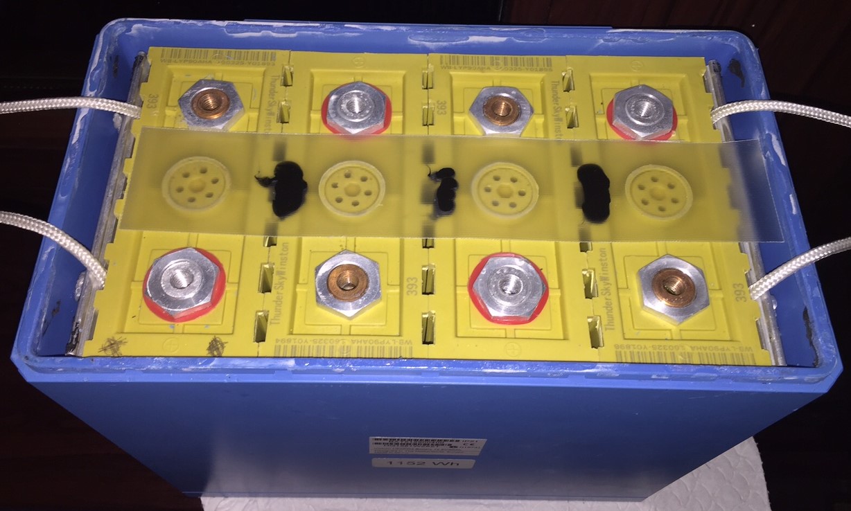
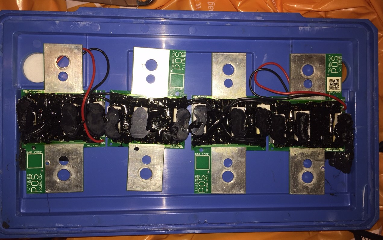
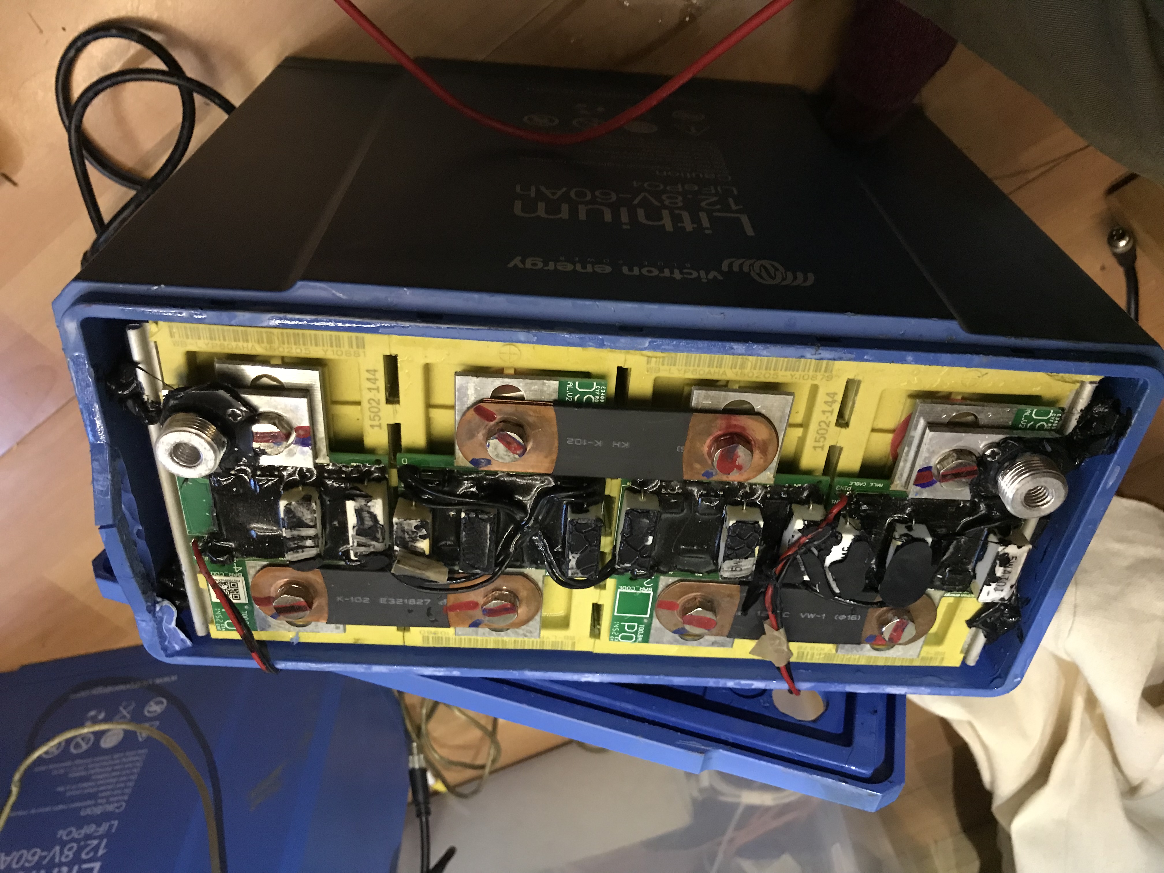
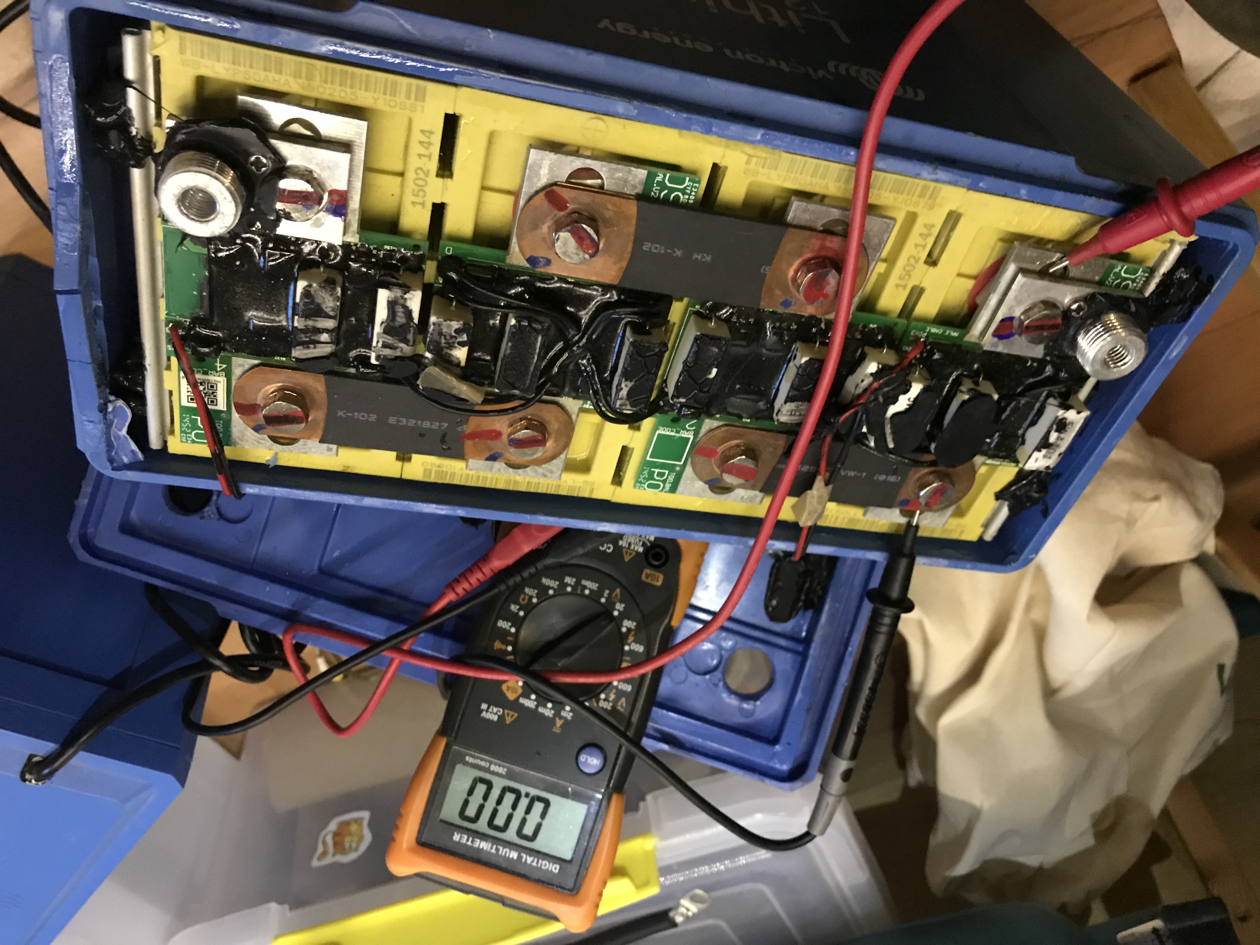
So I took the other battery apart and sure enough one cell was at 0v. I managed to get all the cells out and assemble 4 good ones and put it all back together in the casing. I had to swap one of the BMS PCBs as one got damaged taking the lid off. IT’s all back together now and I’m discharging it a bit as one cell was much higher than the others. Hopefully after that a charge and absorbtion at around 13.7v will balance the cells again nicely. Will have to do a few test cycles. I might run some wires out of the case from each cell so I can monitor the votlage of each cell with the casing back on.
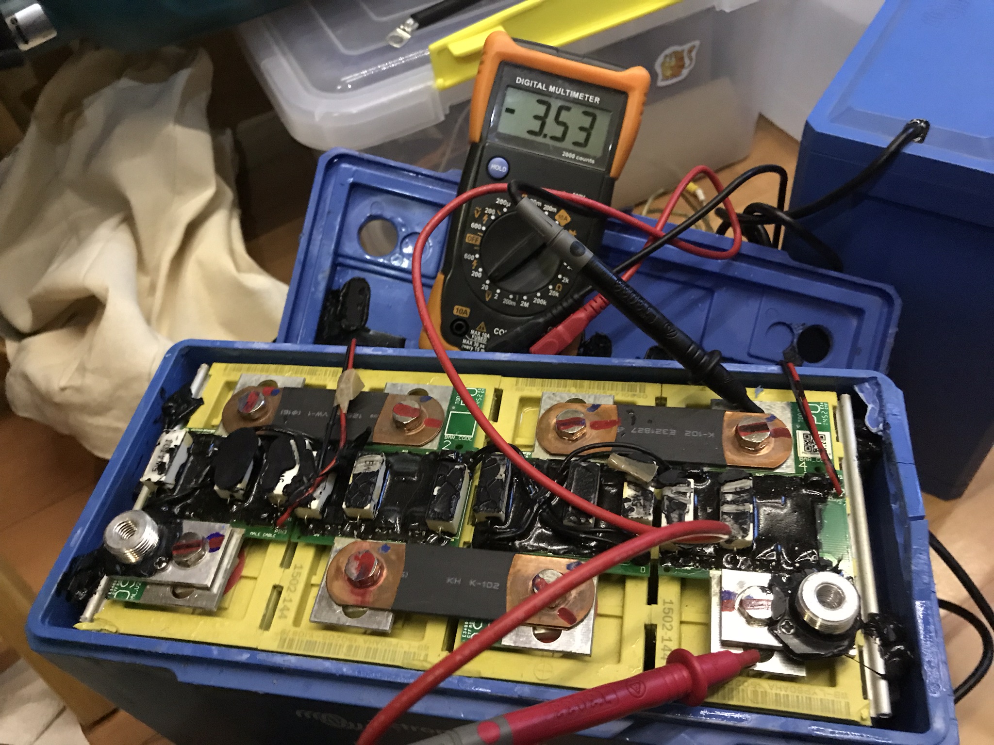

2 |3000

Up to 8 attachments (including images) can be used with a maximum of 190.8 MiB each and 286.6 MiB total.

adev avatar image
adev answered ·

UPDATE: After leaving the new combination of cells for about 30 mins, I then connected the entire battery in parallel to a 12v lead acid batter that was resting at 12.6v (no loads or chargers connected) which allowed the batteries to equalise. After an hour or so the voltage of all 4 cells in the victron had balanced. I then connected it up on it’s own to my 12v system (removing the other two batteries) and proceded to run an average of around 60w on it overnight and into this afternoon. I managed to draw 740wh from it before it got to 12.0v and I stopped - which is about 96% of the rated capacity. A very good result I think. It’s now charging back up by solar but it will only be about 30-40% charged today, so will have to finish tomorrow (weather permitting). The cells seem to be pretty well balanced, just one was at 2.96 when the battery had discharged to 12.0v while the other three were at around 3.02v.


I’ll keep an eye on it all over the next few charge cycles, but so far it seems to have been a successful recovery of one of the dead batteries.

The only dwnside is that the top casing was slightly damaged during the process of removing it.

2 |3000

Up to 8 attachments (including images) can be used with a maximum of 190.8 MiB each and 286.6 MiB total.

scotty9209 avatar image
scotty9209 answered ·

@adev

Superb Post... Please can I ask you advice on this topic?

I have a 90Ah non-smart version with the same problem (Shorted Cell). I have removed the BMS boards, I'm now wondering how you managed to remove the pack of cells from the casing as they seem to be glued / potted around the base of the battery? It looks like there is only a couple of millimetres of compound in the bottom.

I've included a couple of pics so you can see where i'm up to. The shorted cell is the one marked on the Left Hand side.

Many Thanks Scotty


2 |3000

Up to 8 attachments (including images) can be used with a maximum of 190.8 MiB each and 286.6 MiB total.

offgridsa avatar image
offgridsa answered ·

Surprised to see they are Chinese Winston cells in a blue box. I guess they are good cells though.

Surprised that they install the cell interconnects on top of the PCB. Pulling all the load through the cell balancer PCB rather than connecting the cell interconnect directly to the cell terminals.

Is that case damage to the top corner of the end cell all the way through the case?


2 |3000

Up to 8 attachments (including images) can be used with a maximum of 190.8 MiB each and 286.6 MiB total.