question

snakesteve avatar image
snakesteve asked

120/240 VAC shore power charging issue

I have what I believe to be a rather unique shore-power charging issue with the Victron power system onboard my Casita camper.

Background:

My Victron systems consist of the following:

4x Victron 12-volt LiFePo4 smart batteries

1x Lynx Smart BMS

2x Lynx Distributors

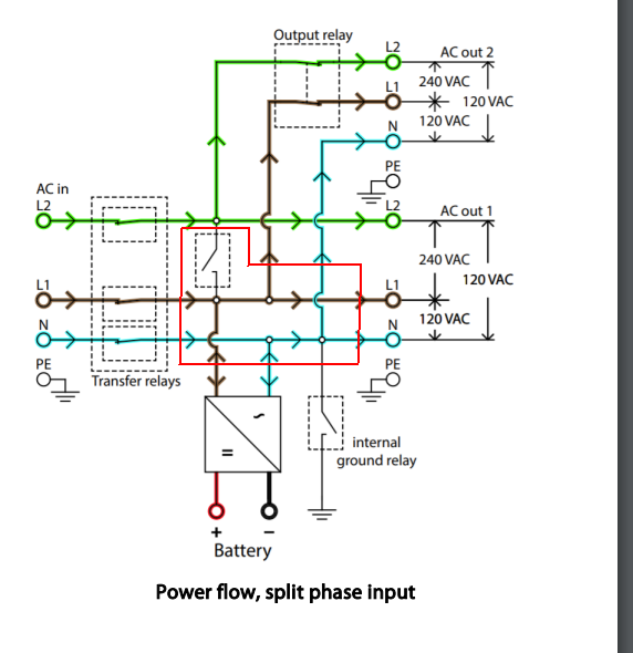
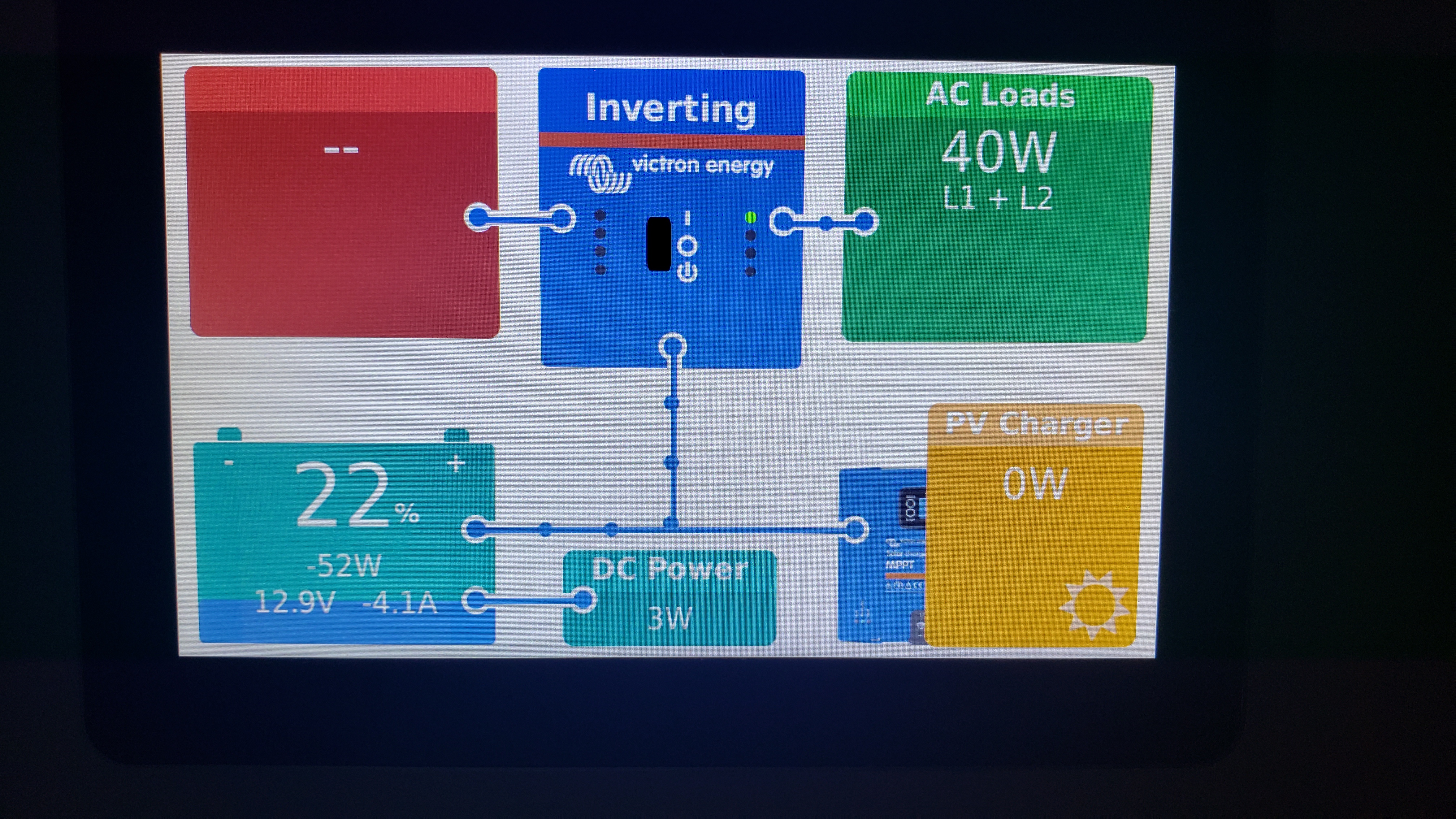
1x Multiplus II 12V/3000 watt Inverter

2x Bluesolar 150/70 Charge Controllers

1x Cerbo GX/Cerbo Touch 50

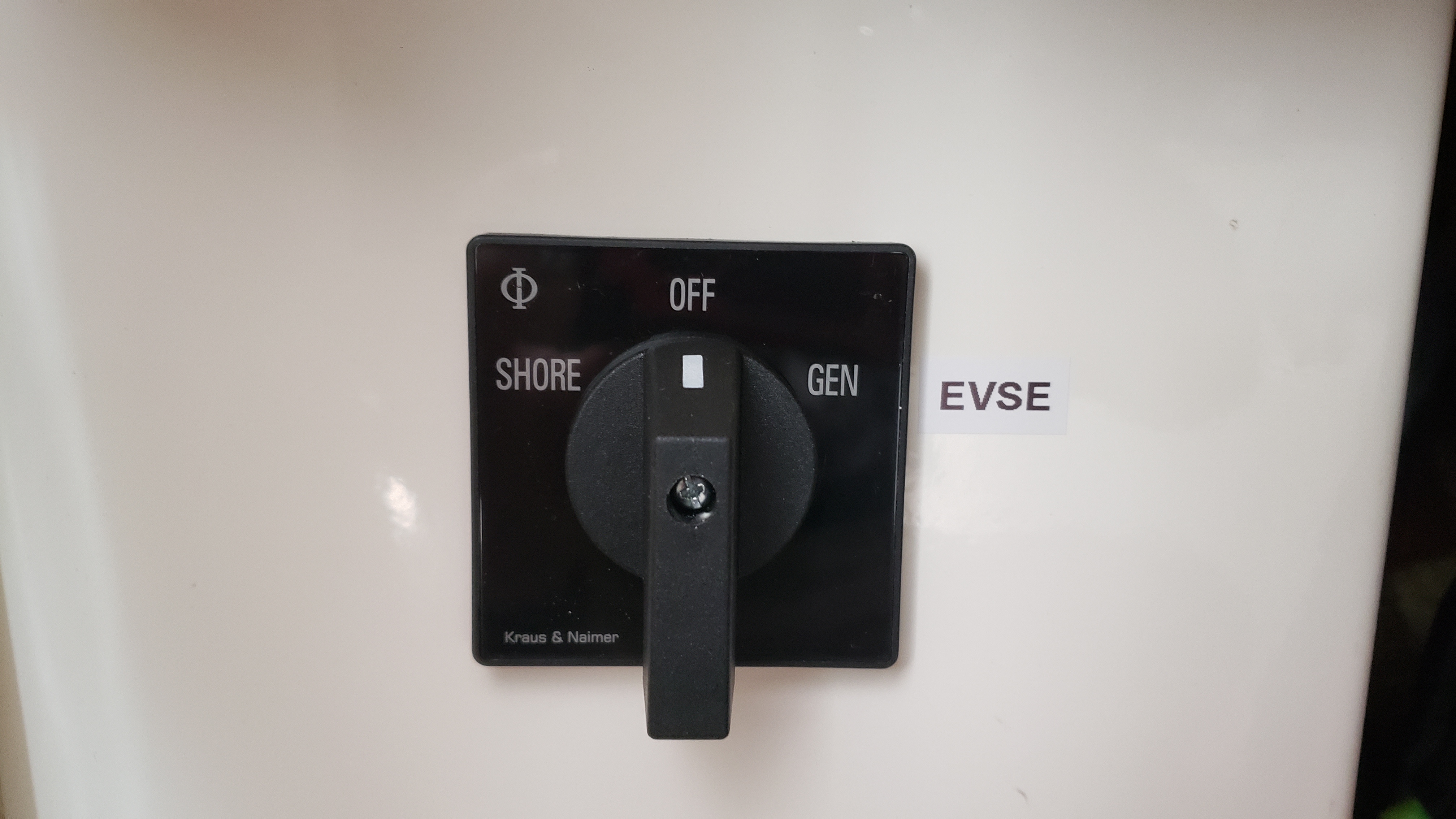
My shore power feeds in via three modes - routed where needed via a Blue Sea Systems 9019 AC rotary switch rated at 240 VAC/65A: https://www.bluesea.com/products/9019/AC_Rotary_Switch_-_OFF_%2B_2_Positions_240V_AC_65A

20230423-164024.jpg

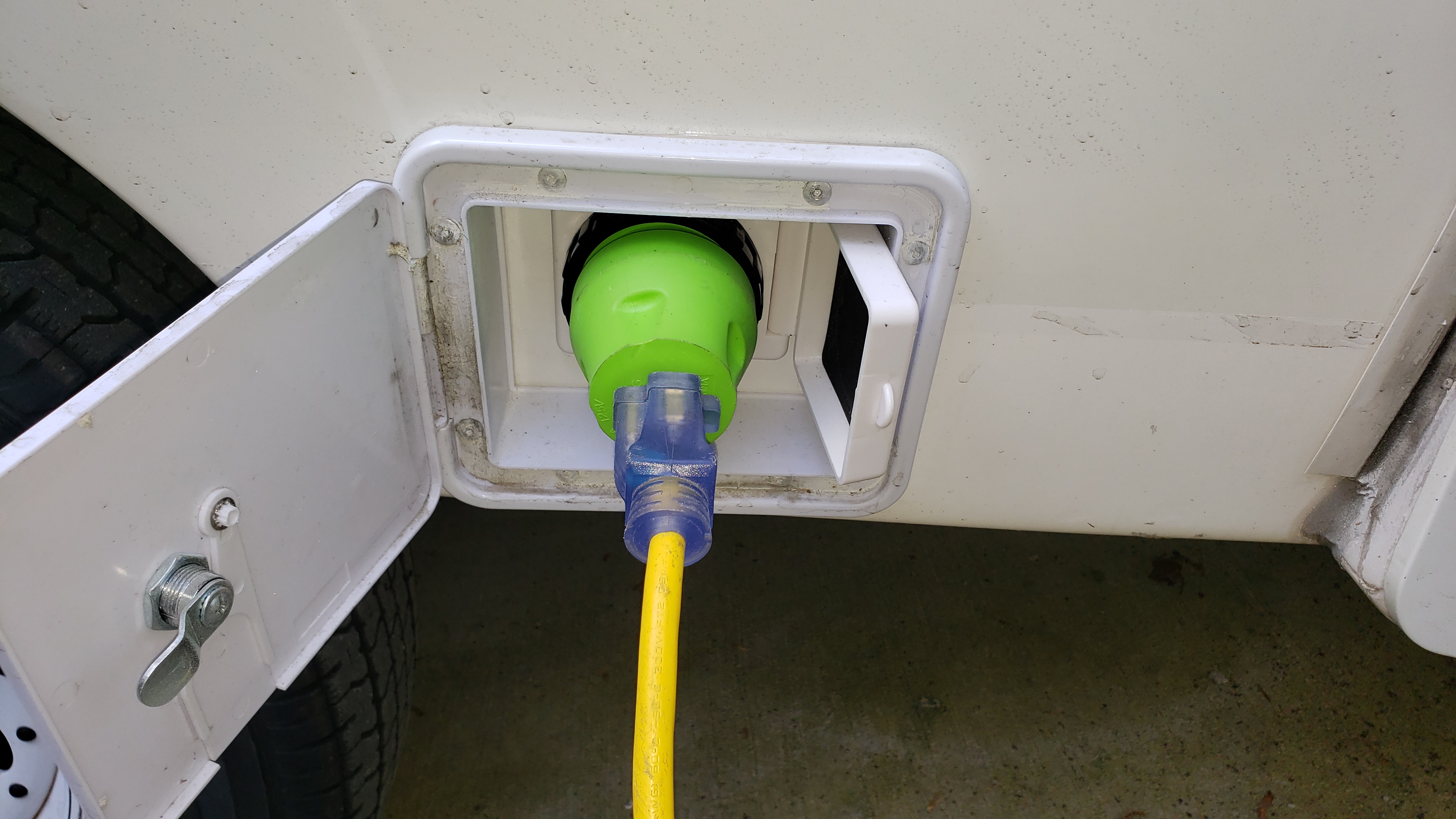
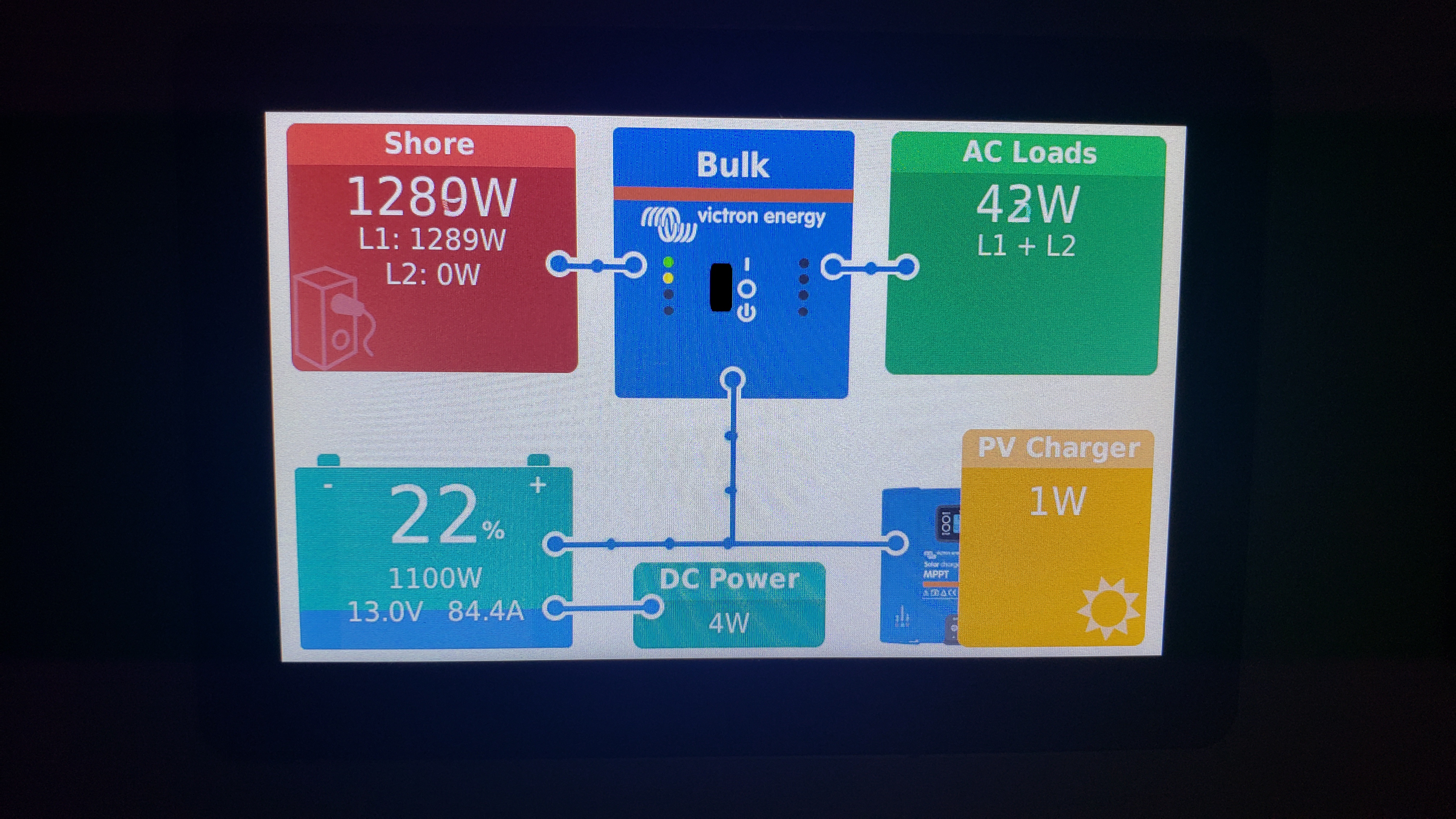
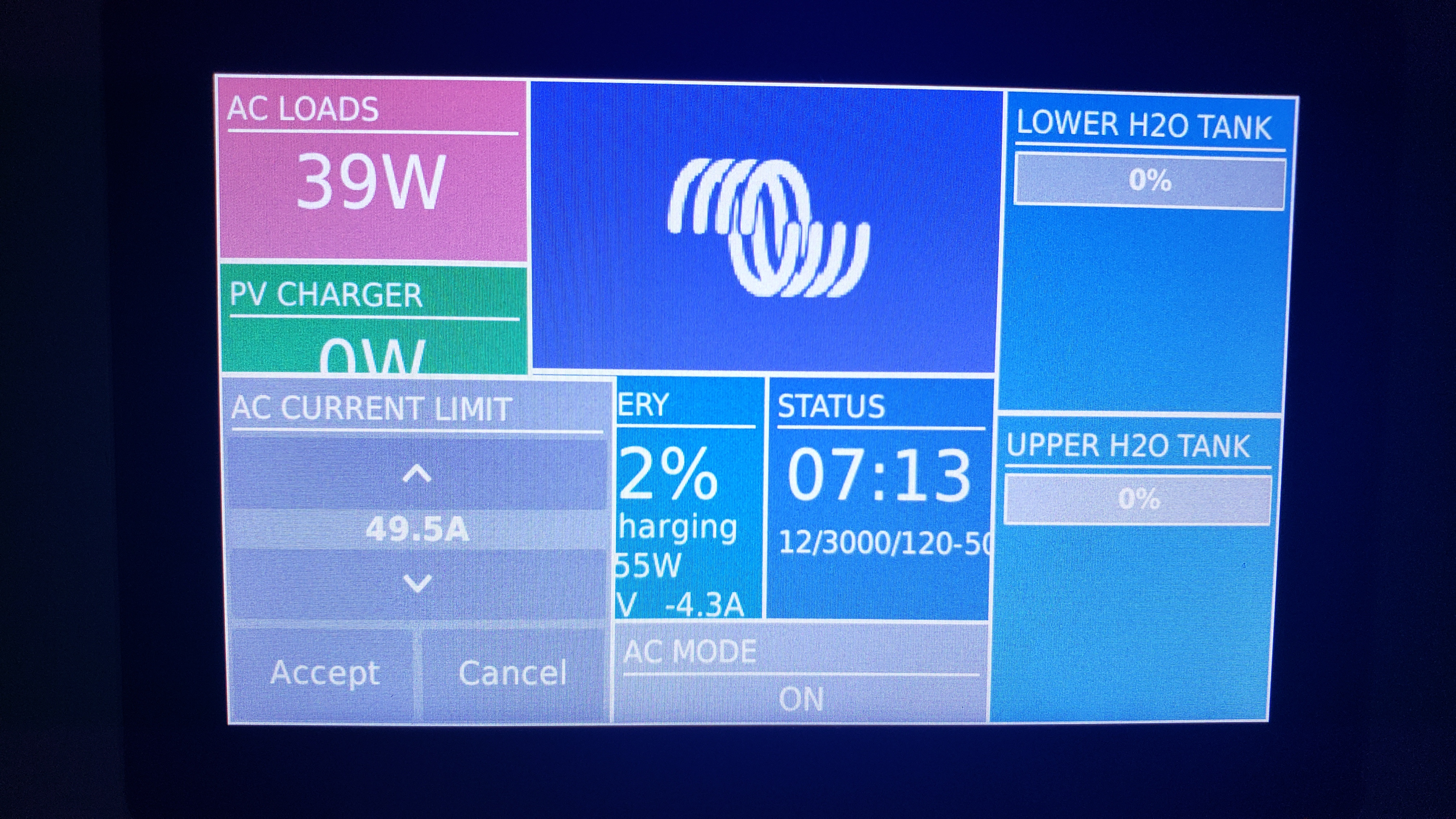
Mode 1 - For trickle charging at home/RV park: 120 VAC via an adapter attached to the external shore-power AC-IN port (working perfectly) – see attached photos of the adapter and Cerbo in 120VAC charge mode.

20230423-182827.jpg

20230425-071917.jpg


Mode 2 - For faster charging at home/RV parks: 240 VAC via the same external shore-power AC-IN port sans 120 VAC adapter. (yet to test)


Mode 3 - For faster charging via electric vehicle supply equipment (EVSE) when on the road: 240 VAC via a J-1772 EVSE-IN port. (does not function) – see attached photos.

20230425-071405.jpg

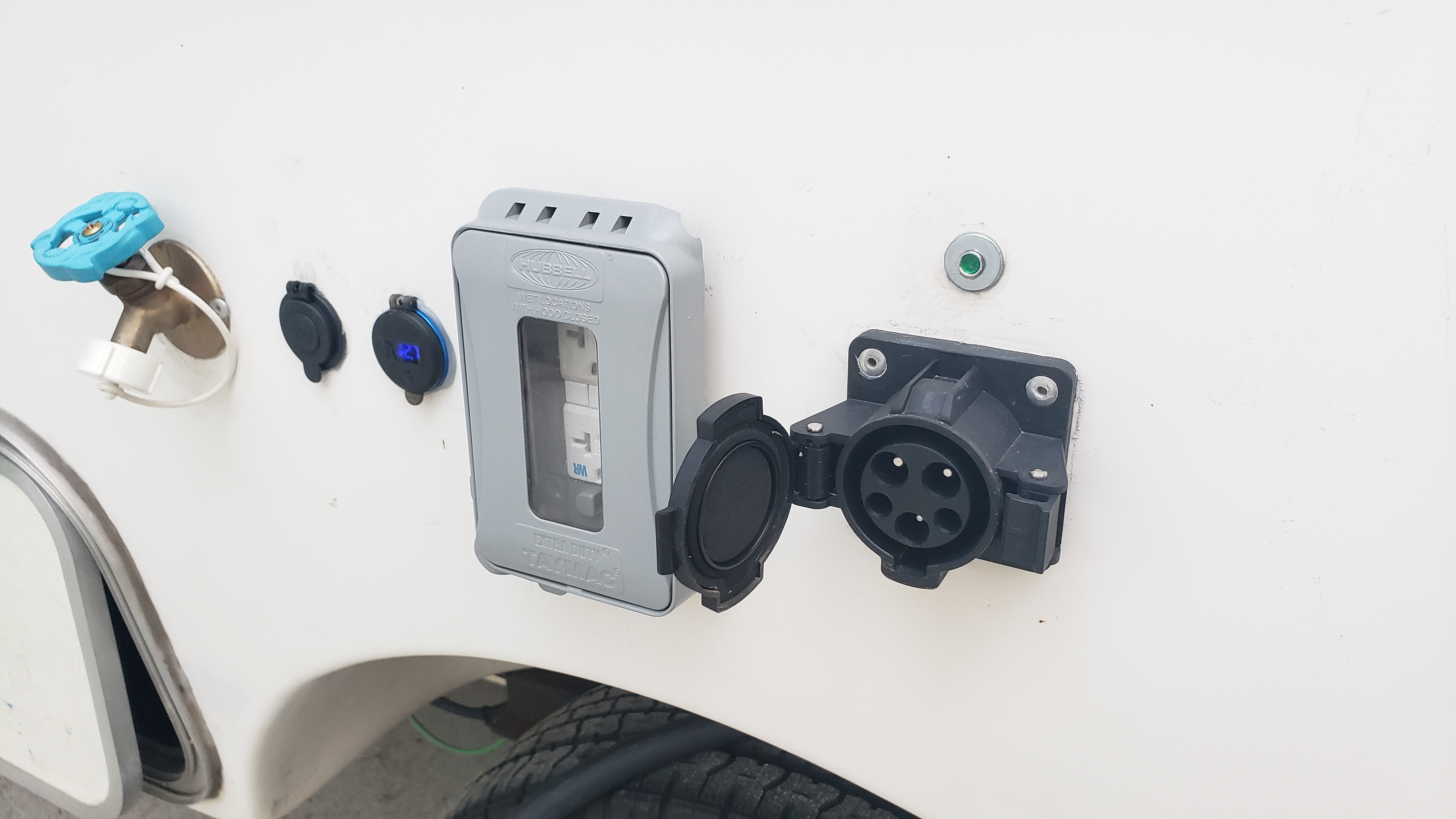
That last AC-IN via J-1772 mode is the reason I am submitting this question.

I have checked all the connections and they are wired properly and secure, and power seems to be flowing to the inverter – at which time the inverter makes a few “relays clicking” sounds – but charging does not initiate - and no warnings/errors pop up from the Victron system. I have tried charging with the AC current limit switch in the Cerbo set at 30, 40, and 49.5A mode – but no luck.

20230425-071330.jpg

20230425-071314.jpg

For reference: The J-1772 adapter I am using is this unit from TucsonEV “J-1772 Adapter with remote pilot box” (scroll ½ way down the page to see the exact 50amp rated unit I am using): https://www.tucsonev.com/ This unit does not have a “neutral” wire so I have some concern that this may be part of the problem.

When plugged into my 240 VAC home EVSE unit, the charge adapter’s active light illuminates green (see photo)...

20230425-071436.jpg


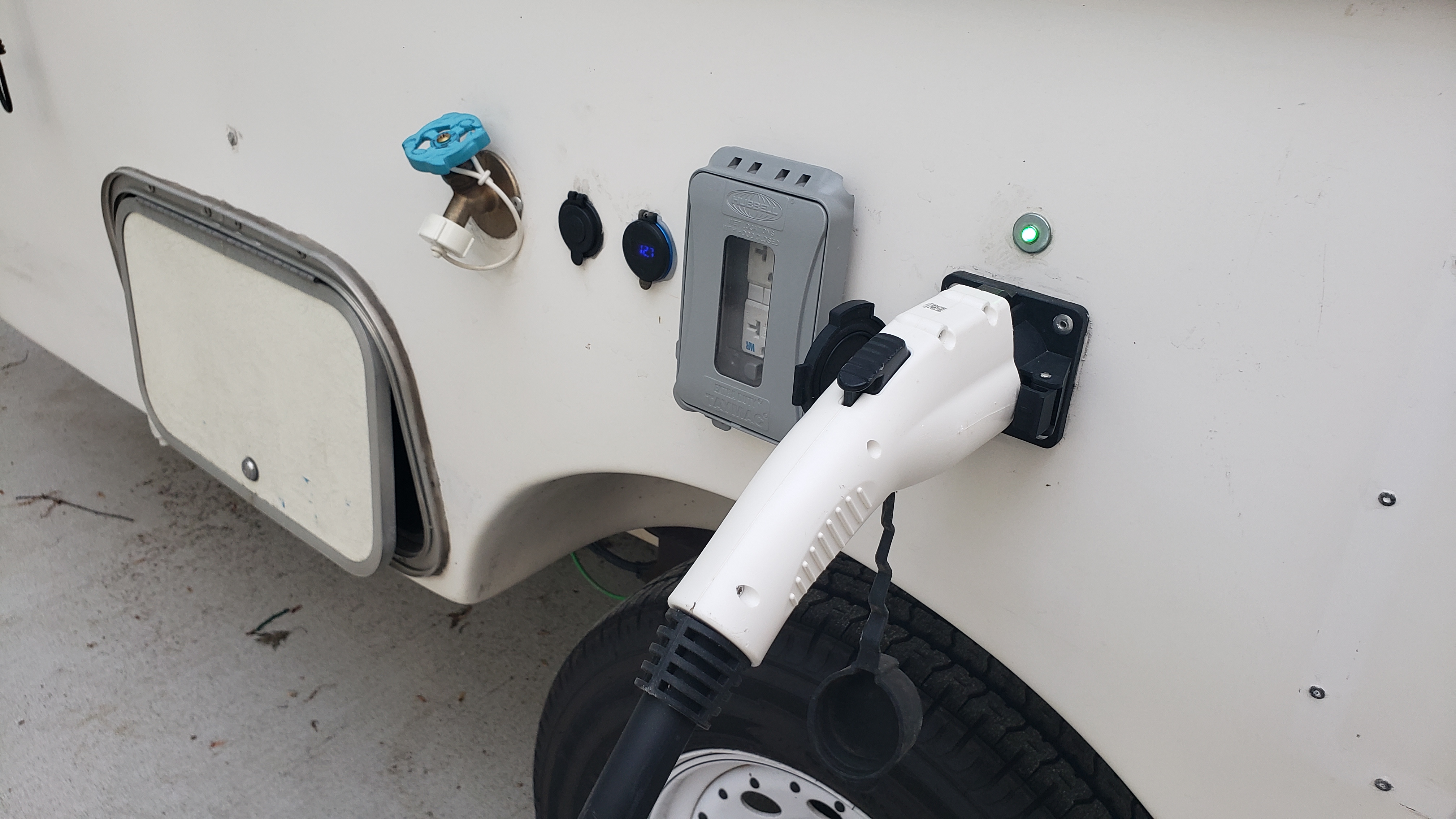
...and the EVSE in the garage makes a “thunk” sound when its contactor closes sending 240 VAC to the J-1772 IN port. I have checked for voltage on the terminals at the Blue Sea systems switch and have 241 VAC - so I know the TucsonEV J-1772 adapter is functioning nominally sending current to the switch and onward to the inverter. Therefore, I feel that the problem must lie in the Inverter’s settings – but I could be wrong.

So, my question is this: Other than in the Cerbo's on-screen current limiting settings, is there a setting in the Multiplus II Inverter’s settings that allows/restricts 240 VAC IN? If so, where do I find this setting and how would you recommend I configure it to allow 240 VAC-IN charging via the J-1772 AC-IN charge port?

I am also a bit concerned that the 240 VAC external shore-power AC-IN port also may not function – but I do know the wiring is correct as the 120 VAC shore power is working perfectly. I will not be able to test this unit's 240 VAC functionality for a few more days.

Any suggestions will be much appreciated.


Multiplus-IIev charging stationshorepower
2 |3000

Up to 8 attachments (including images) can be used with a maximum of 190.8 MiB each and 286.6 MiB total.

3 Answers
Lucian Popescu (Victron Energy Staff) avatar image
Lucian Popescu (Victron Energy Staff) answered ·

Multiple possible reasons, including missing neutral. Another reason might be timing between the internal EVCS relay and the moment when the inverters are starting to charge. If it takes too long, EVCS might give up and open the relay. To test this theory, connect a consumer instead of inverters.

1 comment
2 |3000

Up to 8 attachments (including images) can be used with a maximum of 190.8 MiB each and 286.6 MiB total.

snakesteve avatar image snakesteve commented ·
Thank you for your reply.


Are there any adjustments in the inverter's settings that I can change to allow the Inverter to either accept 240VAC input without a neutral and/or apply a longer time to the interval between plugging in and the inverter starting to charge? Although, when I plug in the 240VAC EVSE charger to the adapter port and hear the EVSE contactor close, the unit then sends 240VAC almost instantaneously to the inverter - so I do not understand how this time interval issue could be the problem.


Or maybe I am just not understanding your assessment of the problem.


What would you suggest I use as a consumer?


0 Likes 0 ·
Lucian Popescu (Victron Energy Staff) avatar image
Lucian Popescu (Victron Energy Staff) answered ·

Something bigger than 1.3kW, that's the minimum a vehicle can use for charging

2 |3000

Up to 8 attachments (including images) can be used with a maximum of 190.8 MiB each and 286.6 MiB total.

snakesteve avatar image
snakesteve answered ·

Hello Lucian, We connected a 30Amp 240VAC electric heater as a consumer in place of the inverter. It has two hot leads and no neutral and our Siemens EVSE powered it without issue. This leads me to believe a setting in the inverter is creating a "roadblock" that is keeping us from using our EVSE to charge our battery bank. How do you recommend we proceed?

7 comments
2 |3000

Up to 8 attachments (including images) can be used with a maximum of 190.8 MiB each and 286.6 MiB total.

I'm, not sure if there is a setting, inverters needs few seconds to synchronize to the grid and probably, the EVCS if not detecting current flowing in those few seconds, it will cancel charging.
0 Likes 0 ·
snakesteve avatar image snakesteve Lucian Popescu (Victron Energy Staff) ♦♦ commented ·

Update:

1 - I have tested the 240VAC "shore power" connection to verify that leg of my system is working nominally - and it works as it should.

2 - I have contacted the manufacturer of the J-1772 EVSE 240VAC IN adapter port and they have stated the following:

"I’m sorry that it is not working in your setup, but I think the problem lies in the fact that none of the Level II EVSE’s produce a neutral.

"...without knowing the specs of the Victron inverter, it is probably looking for a neutral and since there is no neutral input when your rotary switch is on the EVSE setting, it will not work. The contactor clicking are probably the inverter checking and saying ‘nope, no neutral, shut down’".

3 - Therefore, my informed guess is that the problem with the J-1772 EVSE not charging via the adapter lies in the fact that the adapter does not have a neutral and, as suspected by the manufacturer of the J-1772 EVSE IN port, the Multiplus Inverter/Charger is shutting down the inflow of power.

Question: Would an Autotransformer (such as the Victron 120/240 100 amp) placed between the Blue Sea systems 2-position rotary selector switch and the Multiplus Inverter/Charger, be able to bridge the gap between the EVSE and the J1772 adapter (with 2 hot legs and no neutral) thereby allowing the Multiplus to recognize and accept the inflow of 240VAC current?


0 Likes 0 ·
snakesteve avatar image snakesteve snakesteve commented ·

Hello Lucian, Would you be able to offer an answer to my question at the end of my most recent post from yesterday:

"Would an Autotransformer (such as the Victron 120/240 100 amp) placed between the Blue Sea systems 2-position rotary selector switch and the Multiplus Inverter/Charger, be able to bridge the gap between the EVSE and the J1772 adapter (with 2 hot legs and no neutral) thereby allowing the Multiplus to recognize and accept the inflow of 240VAC current from the EVSE/J1772 adapter?

Thank you for your expert insight into this issue.

0 Likes 0 ·
snoobler avatar image snoobler snakesteve commented ·
You seem to indicate a "standard" MP.


Please confirm you you have the multiplus II "2x" unit that intelligently handles switching back and forth between 30A single phase shore and 50A split phase shore.


If so, I assume that you are aware it is just a 120VAC unit that tailors its output based on the input AND it can only charge on L1.


If you feed an AT with single phase 240VAC, it can output true 120/240VAC split phase, which could then be input into your inverter. However, while the AT may have a 32A or 100A L1-L2 rating, it only has a 22A L-N rating, i.e., the difference between the two legs can be only 22A, or in other words, there can not be more than 22A on N.


0 Likes 0 ·
snakesteve avatar image snakesteve snoobler commented ·
Yes, it is a Multiplus II 2x. 120VAC inverter/charger.


Thank you for that information.

I have another question: When the Multiplus II 2x inverter/charger is charging the battery from 240 VAC shore power, does the Multiplus use both hot legs at 240VAC balanced to charge the battery, or does it use just one 120 VAC leg to charge the battery?


0 Likes 0 ·
snoobler avatar image snoobler snakesteve commented ·

Per my above reply, it only charges from L1.


L2 is either shorted to L1 when absent on the input or passed directly to the L2 leg. It only goes through a transfer switch, not the inverter itself.


Conceptually, I have sketched in the inverter with red lines:


1683571755471.png

L2 essentially goes around it.

Charging uses the same transformer as inverting. It can only charge and invert on the single 120V transformer it has.

The only advantage to charging on 50A power is the 50A input vs. the 30A input.

0 Likes 0 ·
1683571755471.png (88.9 KiB)
victrongsmr avatar image victrongsmr snakesteve commented ·
Were you able to resolve this EVSE issue?
0 Likes 0 ·