question

matt1309 avatar image
matt1309 asked

Installation Design: Voltage drop over long run

Hi Folks,

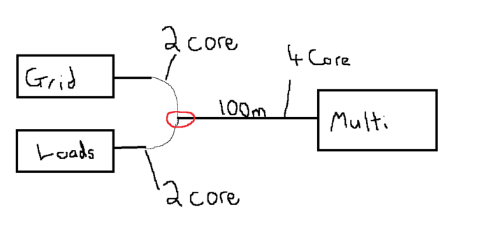
Working on plans for expansions to a solar installation and it's a little tricky. The installation location is 100m from grid input and majority of the loads.

ie grid -> 100m -> 2x multiplus -> 100m -> loads.

but grid -> majority of load = 2meters....

And automatic switchover if grid failure or vice versa if batteries at 0 SoC is required.

Question:

1. Voltage drop: I see people talk of voltage drop being a concern, When people say concern is it just the voltage being too low for devices to operate properly/higher current drawn? If so to reduce concern on run from multiplus -> loads I could just increase the output voltage right? Are there any other "Concerns" in regards to voltage drop I should be factoring in?


2. System design/wire runs: The run from Grid to Multi and back to loads could be 200m on passthrough in the event batteries are empty. (My plan is to minimise impact of this was by using grid to charge batteries when below x SoC so that it's rarely pure passthrough and more often than not the grid charges batteries and then gets inverted to the slight the higher voltage say 245/250 ish). Is there a better solution?

I was also thinking maybe a configuration with an auto transfer switch or anti-islanding device might be better to cut out the 200m but struggling to think of a clean way of configuring that with the multiplus. Anyone had similar experience with setups like this/got any nice solutions that I'm missing?


Would it be something like?

grid -> ACIN multiplus -> ACOUT to ATS -> loads

grid -> ATS -> Loads

Don't know why but this just feels to add more complexity.... Not sure if instead I'm over thinking the issue of the run length, and maybe i just round up on conductor size and live with it?

Multiplus-IIsystem designvoltage dropanti islandingats
2 |3000

Up to 8 attachments (including images) can be used with a maximum of 190.8 MiB each and 286.6 MiB total.

3 Answers
daza avatar image
daza answered ·

This is how I’ve joined me grid and the inverter return to the houseimg-3854.jpeg
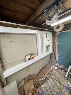
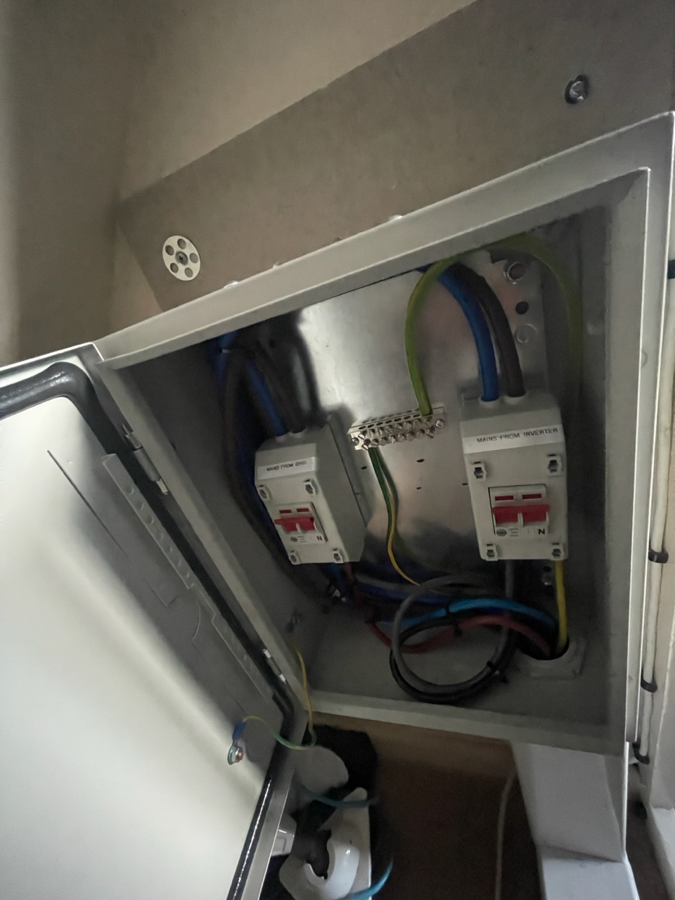
No 5core on a single phase, I had to return the earth rod earth to the house as the house didn’t have the DNO one anymore, I’m doing the whole house critical load. And my run is max 10meters. My system is a work in progress I’ve just finished the wiring for the house and garage in preparation for inverter DNO got to attend to change the Fuse for 100amp.


Yes voltage drop means resistance in the cable which equals more heat in the cable from the get go and if your sustaining the load it only equals trouble later ie cables burning out/fire


I see what you mean is it 100Amps your looking to get load side? How are you joining the DNO supply to that 4 core? But looks like you will need a bigger cable diameter anyway, Split the load CU instead of 100Amps going to one board I’m assuming it’s a 100amp as your on single phase but that would require another cable but even on 35mm your looking at a 12volts drop which may cause issues some electrical devices on 100meters are you sure that’s the distance of the cable?.

I would look at running a duplex board load end and thinning out the loads equally between sides but you’re still looking at a heavy chunk of change for new cable even and board to get the amps down. Looking on the calculator if your 50amps 100m then you can do 25mm SWA but that would require another set of cables of 4 core run to the load end.

I’m using the Doncaster cable calculator which have suggested that if it’s 100meters at 100Amps then your looking at 50mm that’s a hell of a cable let alone the connectors to connect it and the bend radius of that cable into a house. At 100meters think duplex board is the cheapest route with the additional cable. I know it’s more questions than answers but I think you need to be a 100% on distance as it will cost you if you have over compensated on distance.


img-3854.jpeg (254.3 KiB)
3 comments
2 |3000

Up to 8 attachments (including images) can be used with a maximum of 190.8 MiB each and 286.6 MiB total.

matt1309 avatar image matt1309 commented ·
Thanks for detail @Daza nice to hear someone coming to similar numbers. I really like the split CU idea, I had blinkers on wire size and hadn't really considered that. I think that's the solution long term.


Realistically I don't think I'll be anywhere near 100amp load, the current supply is only 60a and loads have never come close to that.

I think the conclusion I've come to is to go with 4 core 25mm2 (maybe 35mm but that'll be max, I agree anything more i think I'll not only struggle with price but also connectors and bending radius). I'll then limit grid usage to around 50amps and then ensure that passthrough isn't used and instead set it up so that batteries are charged by grid and then inverter power loads rather than every letting passthrough occur.


I do really like your idea of split CU idea though. It seems the best of both. At my current loads the 4 core 25mm or 35mm will be sufficient and I should be able to run whole house as critical load but then if I do ever increase loads a second CU running on grid or even grid paralleled with ACIN with on multi could be the ultimate solution to my problem wouldn't be breaking the bank.


Thanks agian!!


0 Likes 0 ·
daza avatar image daza matt1309 commented ·

Yeah that sounds like a plan I split more board into three parts as I had to power my garage so I have the garage Duplex CU where all the loads are split ie mains inverter and then run back to the house 20way CU here is mine but still work in progress as I need to get the Cerbo GX unit and other stuff that’s why I’ve not cleaned up yet. You see what I mean about bend radius and that’s only 5core 25mm
img-3855.jpeg

0 Likes 0 ·
img-3855.jpeg (36.0 KiB)
matt1309 avatar image matt1309 daza commented ·

Ohh wow, yeh see what you mean. That could be a headache for me. I might see about terminating a jb outside and then bringing flexible cables in via a bigger hole in the wall. Will be a main drilling it out but if that's 25mm 5 core. I don't think I'll stand a chase with 4 core 35mm!


Thanks again @Daza really helpful!

0 Likes 0 ·
daza avatar image
daza answered ·

Can you draw a diagram of the system layout, and with what section is 200m. But as a matter of course I would run the grid sized cable to your isolation switch. How I’m wiring mine in the UK I have two isolation switches for the inverter the inverter input that runs off of the 50amp I have run via 10mm to the isolation switch which is max 2m away the other side from the inverter output isolation switch is wired up in 25mm because of the 70amps that I could potentially go too all over kill but shouldn’t have issues with voltage drop. PS I had to use 5core 25mm to sort out my grid connection so I could move the supply to a different location and then go back to where the source started with the inverter output expensive but that’s the only way to move 100amp feed to another location in the UK other than asking the DNO to move the supply head which would be a hell of a lot more.

1 comment
2 |3000

Up to 8 attachments (including images) can be used with a maximum of 190.8 MiB each and 286.6 MiB total.

matt1309 avatar image matt1309 commented ·

Thanks @Daza ,

Sounds like you've done similar to what I've planned. How long was you 5 core 25mm out of curiosity, do you ever use passthrough or do you always have some draw from batteries?

My concern was the scenario where battery is empty and grid is being passed through to loads. That would be near 200m (see terrible MS paint drawing below). Is the voltage drop too large over that distance. However I suppose i should never need large draw from grid if i just make sure batteries charged overnight


Grid and Loads are next to each other. However Multiplus ii is 100m away. Similar to you but I'd use a 4 core (I'll use earth rods rather than export the earth save me the 1 extra core). Or when you say 5 core do you mean 3 phase + earth? My setup would be single phase and I'd have 2 cores to connect ACIN on multi to grid and 2 cores for connecting to (critical loads) via ACOUT.


From calculators I've seen they seem to suggest 5% voltage drop the max I'd get out of 25mm is 8kw which sounds low on it's own but I think I'm overthinking it as it would be 8kw + multiplus.

I agree asking the DNO is not viable for me (££££).

The red circle is not connecting grid and load, ie they're not in parallel. (I don't have the MS paint skills to add in the relevant breakers etc)

2 cores from Grid are going to ACIN, remaining 2 cores in the 100m 4 core go backto loads.

1682064542545.png


0 Likes 0 ·
1682064542545.png (21.6 KiB)
marcve avatar image
marcve answered ·

I would be carefull with increasing the voltage. With a high load, the voltage will be pulled down to the correct voltage, but with a low load, it will be close to the set max. Always good is running the correct gauge wire for load and distance. For charging the batteries is not a problem, because the inverter will always adapt to the much lower output dc voltage and keep it stable.

2 |3000

Up to 8 attachments (including images) can be used with a maximum of 190.8 MiB each and 286.6 MiB total.

Related Resources

Additional resources still need to be added for this topic

MultiPlus-II Product page 

MultiPlus-II Manual

MultiPlus-II 230V Datasheet 

VE.Bus Error codes