Hi
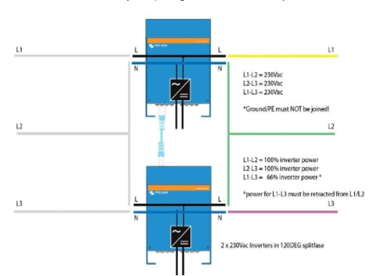
I know that 3-Phase Delta is not supported. But what about using 2 inverters in a 2-phase configuration with 120 degrees shift? The goal is to be able to feed in more than the max 16A on a single phase limitation we have here in Norway, and still be able to control everything from one single Cerbo. I have no need for a real 3-phase network on the back side of the Multis. Some single phase critical load on one of them is basically enough. The second Multi should only act as a grid-tie inverter on a different phase to even out the power between the phases.
I got this drawing from a Norwegian Victron distributor. I assume it comes from Victron. I understood that this was somehow tested, and it works. There were some instabilities in the voltage on large load variations between L1 and L3, but except from that it worked. This setup may work in an non-ESS environment, since you can disable the N-PE ground relay. In ESS-mode you cannot disable the relay, and you will short L2 and L3 to PE on the output. The picture also states that "Ground/PE must not be joined"
So what if we modify the above slightly to something like this:
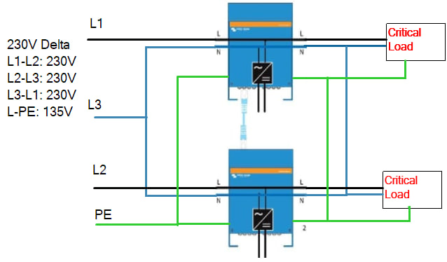
It is possible that the phase rotation will be wrong on the second unit. I'm not sure, but if we assume this is ok, this would allow ESS and feedback. In case of a grid failure, it will look like this:
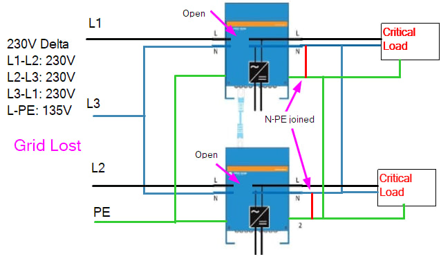
The internal relays will disconnect the inputs. The ground relay will kick in and join N and PE. Since we here have a common phase for N (the L3), this will not short out anything. It will create 2 separate single phase TN networks on the output. As long as you don't connect any load between the 2 inverters I cannot see that that is more problematic than running one single unit, which works fine.
Can anyone here confirm if above solution will work or not?
-Øystein