Hi All -
I was wondering if anyone has figured out a way to use a battery protect or another device to disconnect at an over voltage situation, i.e. battery goes over 25.2V ( Tesla Module ), like the battery protect will do when I hit 19V on the low side.
asked
High Charge Voltage Disconnect - Battery Protect ?
If the BMS has an output contact why not use a DC contactor. if the BMS has no contact then maybe BMV plus a DC Contactor or Build your own BMS
https://hackaday.io/project/10098-model-s-bms-hacking
https://www.diyelectriccar.com/forums/showthread.php/tesla-bms-190266.html
There are even Latched (don't consume any energy while closed or open ) Bistable ( no energy consumption in both states) contactors
https://www.ev-power.eu/DC-Contactors/
https://www.ispacetek.com/DC-Contactors.html
Please note:
-BP is not to be used between inverter and battery (inrush current too high)
-BP only works one way
For protection of a lithium battery, a good way is to use a 'trip unit' to disconnect, I use a standard breaker with trip unit connected to it, the bms triggers the trip-unit if values go above / below the maximum settings (cell voltage, temperature). In normal circumstances this should never happen (inverters / chargers should listen to the BMS) so this is a good last resort. needs manual intervention to re-connect the battery.
Hello Boekel, Can yoo share which standard breaker with trip you use/suggested?
I just found out the "hard way" on the BP placement. I tried to use it between inverter and battery. When I disconnected from shore, after about a minute, the lights started to flicker and house DC power dropped to about 8vdc. The BP would show code "E1" (short circuit). My thinking was that I was needed a back system to keep the inverter from over-drawing the batteries like the DC house load could.
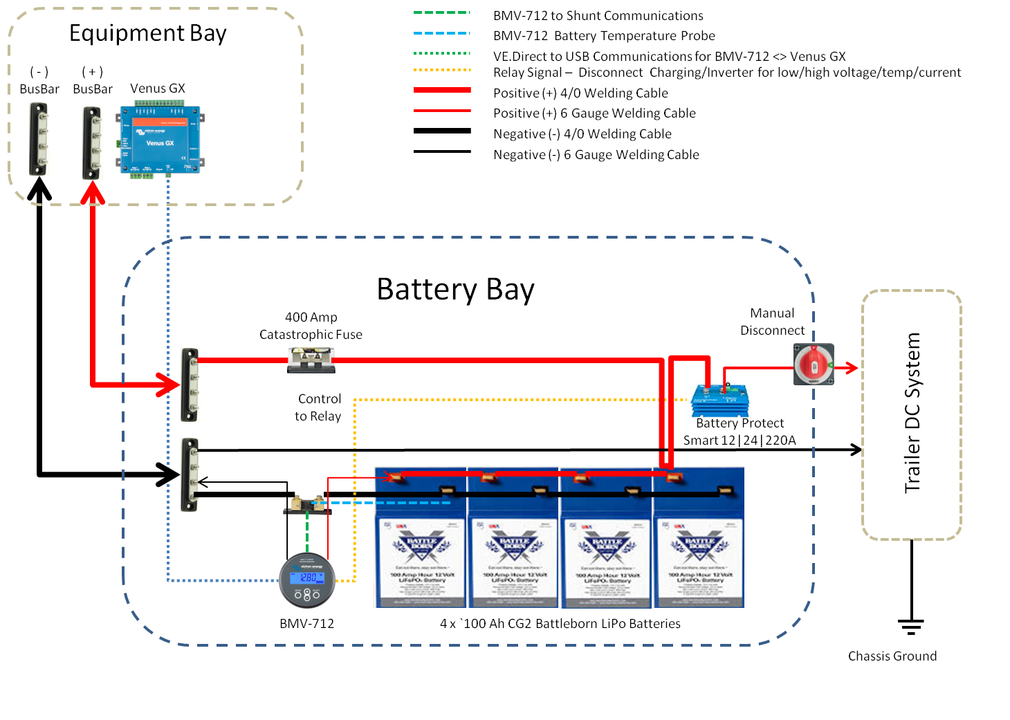
I have a 300 amp breaker for over current between inverter-battery. I guess I'm going to have to rely solely on the low voltage disconnect logic in the inverter itself. Or, is there a better way?
I attached my before/after pics for the "wrong way" versus "right way". All of the equipment was safe. I just spent too much on the BP. House DC never will be above 65Amps.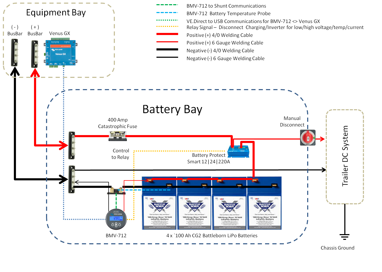

If you are connecting them to a Multiplus then you could use the VE BMS to turn the charge or the load on and off, but you still need to sent the signal to the VE BMS unit this is easy to do as the connection sensing wire is a loop and there is a HV and a LV loop wire so its just a matter of open circuiting them when you want.
this way you don't need a solenoid or a BP if its ONLY the inverter charger and its controlled by the VE BMS unit connected that is and no other small loads,