question

in2pharma avatar image
in2pharma asked

Solar Charger terminals caught fire

272160a4-a76a-43a2-b4d0-4e4e5af9c626.jpeg
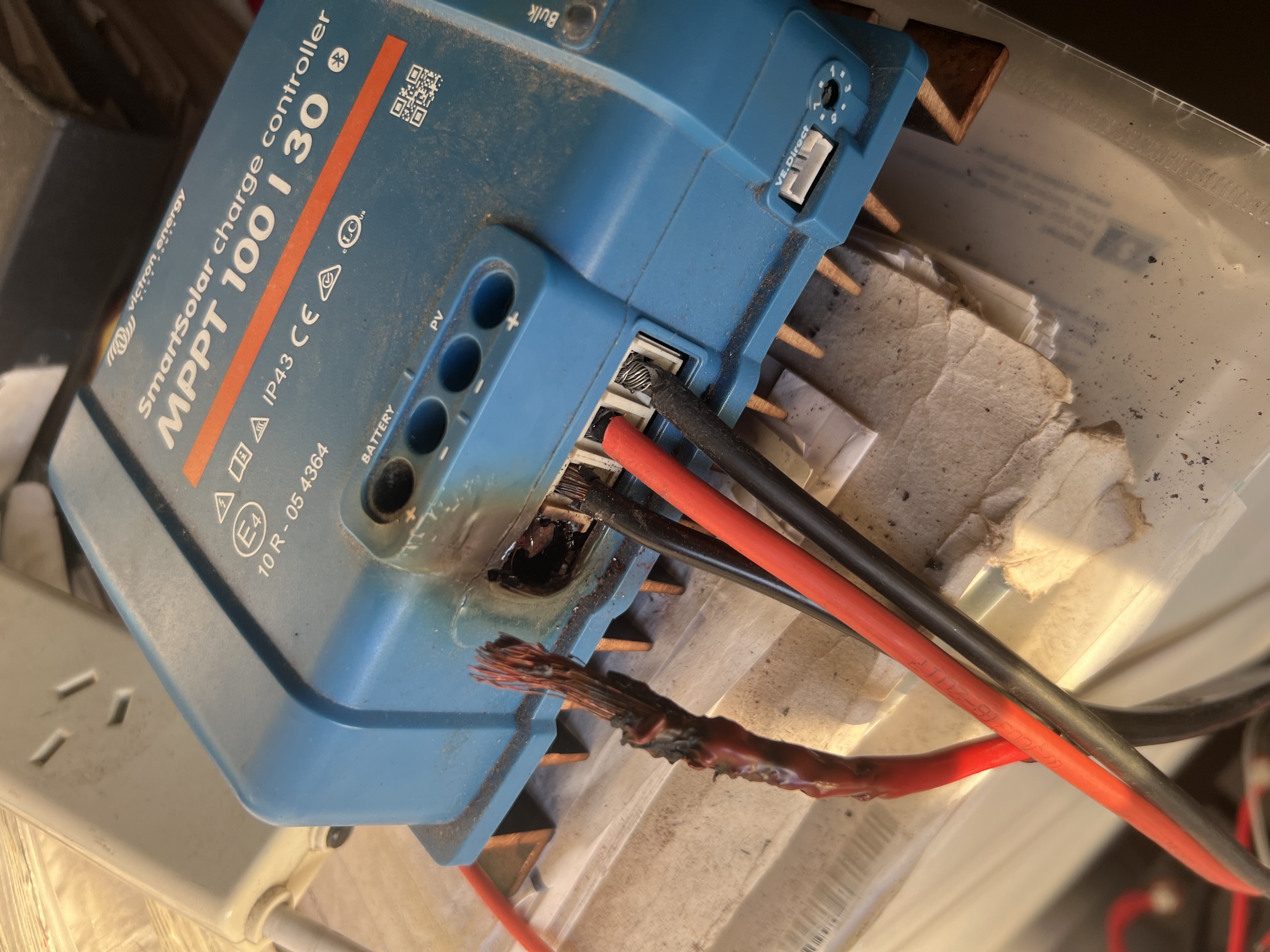
Has anyone had their solar charger catch fire. We have been using the unit without incident for about 12 months and today I could smell a weird electrical smell. Approached the area to see flames starting to be emitted from the solar charger. Thankfully I caught it in time however it could have been a disaster.

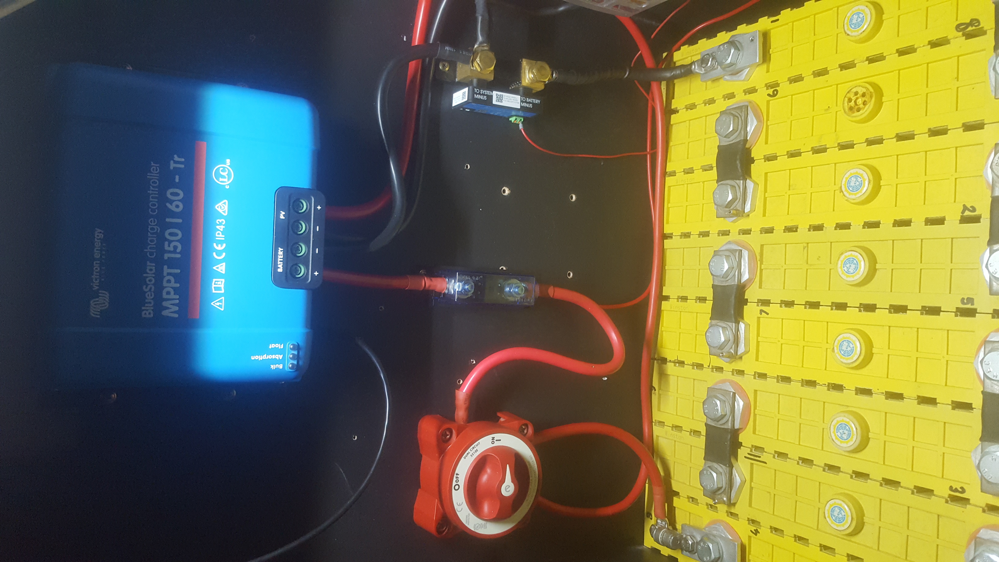
I know the wires look loose. They were pulled with force to try and disconnect the battery and panel from the smoldering charger. On install they were cut to size and tightened as per the instructions Photo was taken post panic after the smoke cleared.

MPPT Controllersfireshowcase
2 comments
2 |3000

Up to 8 attachments (including images) can be used with a maximum of 190.8 MiB each and 286.6 MiB total.

teloth avatar image teloth commented ·
Coarse strand wire badly installed
2 Likes 2 ·
Alexandra avatar image Alexandra ♦ commented ·

For future plans include a pv and dc disconnect breaker near the mppt, so you can cut off the current source for charging and the battery.

The pv one being the important one.


1 Like 1 ·
5 Answers
Alexandra avatar image
Alexandra answered ·

@In2Pharma

I have seen this once or twice on systems we have been called in to troubleshoot. Not just Victron sites, and can happen on AC wiring as well.

When things are not torqued to specification and checked periodically you get loose terminals. Loose terminals get hot... Hot can equal fire.

Not a victron fault, a user/installer error.

2 |3000

Up to 8 attachments (including images) can be used with a maximum of 190.8 MiB each and 286.6 MiB total.

nickdb avatar image
nickdb answered ·

Looking at the PV wiring, apart from reversed wiring colours (red -'ve black +'ve), the positive cable is a seriously nasty connection. If the battery wiring was similar, it is no surprise it caught fire.

Sloppy installation = increasing heat over time = fire.


10 comments
2 |3000

Up to 8 attachments (including images) can be used with a maximum of 190.8 MiB each and 286.6 MiB total.

in2pharma avatar image in2pharma commented ·
Probably should have mentioned in the initial post that the wires were pulled with force in an attempt to disconnect them from reg solar charger. No they weren’t installed with the wires showing. They were cut to size however I didn’t have a screwdriver on me when my bedroom was almost catching fire so I had to think quick and work with what I had.
0 Likes 0 ·
klim8skeptic avatar image klim8skeptic ♦ in2pharma commented ·
@In2Pharma What is the serial # of the mppt? Trying to pull up an appropriate manual.
0 Likes 0 ·
in2pharma avatar image in2pharma klim8skeptic ♦ commented ·

image.jpg

Photo included

0 Likes 0 ·
image.jpg (1.3 MiB)
klim8skeptic avatar image klim8skeptic ♦ in2pharma commented ·

@In2Pharma This is the closest manual I could find to your build date. Smartsolar MPPT_100_30-50 manual 06-20.

Plz ensure that you install as per manual.

cleanshot-2023-01-17-at-182400.jpg

0 Likes 0 ·
smallsolar avatar image smallsolar klim8skeptic ♦ commented ·

My question after reading that, especially for the PV wire is how to safely use common CSA approved 10 AWG wire found here in Canada. (I say common because I got the same Southwire 10 AWG, 19 strand PV wire from two different suppliers at different ends of the country, but maybe I'm wrong) The wire looks mostly like the middle wire in the manual pictures (see attached) and each strand has a diameter of about 0.5 mm, which according to the manual is a no no. I can understand Victron wanting to mitigate risk, especially for higher amperage applications, just wondering why the wire I was sold by "PV suppliers", in one case a Victron authorised supplier, wouldn't meet their specs even though it is CSA approved.

I guess for myself, short of finding new wire, is there a way to more safely use this wire, assuming of course properly torqued terminals periodically inspected? Ie, would it be wise to install ferruls soldered to the wire for the MPPT connections? Or use a conductive paste on the wire?

See the attached photo for the wire I am talking about. For reference it is being used with a Victron 100/20 and Victron 100/15 which manuals both have the wiring section posted by klim.pxl-20230120-194903901.jpg

0 Likes 0 ·
klim8skeptic avatar image klim8skeptic ♦ smallsolar commented ·
@SmallSolar @In2Pharma @Guy Stewart (Victron Community Manager) In your application I would run that solar rated cable from the array to the PV breaker.

Between the PV breaker and the mppt you can use the cable specified in the mppt manual.

0 Likes 0 ·
von-baron avatar image von-baron klim8skeptic ♦ commented ·
Another idea might be you crimp lugs on the end of the 10AWG 19 strand cable on both zero and positive.


Then go to terminal post for the zero volt line and to a breaker for the positive side.


Then as klim8skeptic says, take fine multi strand cable as specified from these two point to the MPPT charge controller.

Avoid at all cost the use of jaw type screw down terminals type connections.

Cables that have been lugged and held by threaded rod, washer and split washer and nut will provide a more reliable solution.

I use a small hand pumped hydraulic crimping tool, which makes the best crimps and is easy to do, even in small tight spaces that would not be possible with a manual crimping tool.

0 Likes 0 ·
smallsolar avatar image smallsolar klim8skeptic ♦ commented ·
Good suggestions from both thanks. Wouldn't that just push the supposed bad connections to the breaker on the PV side though? I guess it does reduce the potential failure points.
0 Likes 0 ·
klim8skeptic avatar image klim8skeptic ♦ smallsolar commented ·

@In2Pharma@SmallSolar PV breakers are designed to accept PV cable. Follow manufacturers instructions tho.

0 Likes 0 ·
nickdb avatar image nickdb ♦♦ in2pharma commented ·
This is why fusing and isolators are required for safety.

Terminals only heat up where there is bad contact, something that cascades over time.

0 Likes 0 ·
sharpener avatar image
sharpener answered ·

Does the photo show the MPPT in its installed orientation? It looks to be horizontal, this will badly affect the convection cooling.

6 comments
2 |3000

Up to 8 attachments (including images) can be used with a maximum of 190.8 MiB each and 286.6 MiB total.

von-baron avatar image von-baron commented ·
If it was, I am surprised the pile of paper it sits on did not also catch fire.

It is a simple case of a bad install, wrong wire type, wrong wire colours for the PV side and wrong torque on the terminal screws.

As nickdb stated, why on Earth, are the PV leads coloured wrong?

To me, looks to be here in Australia, from the power board nearby.

I would suspect the solar charge controller will be otherwise fine, just with badly burnt terminals.

Quite amazing, it shows what a small 30 amp unit can do in terms of damage.

Yes, a fuse disconnects or isolation switch is needed in here. Buy one right away and consider yourself lucky.

1 Like 1 ·
klim8skeptic avatar image klim8skeptic ♦ von-baron commented ·
@von baron Got some photos of your install you would like to share??
0 Likes 0 ·
von-baron avatar image von-baron klim8skeptic ♦ commented ·

Klim, for my system, I am currently going through a change from 8 cell LeiFePO4 to 16 cell LiFePO4 set up, so 51.2Vdc and am part way through the upgrade at this stage over the past week, so not finished yet.

The battery system is made up of Winston 400 Amp/hr cells.

My previous solar controller was my own design, 32 bit micro-controller based together with CAN bus to a ZEVA BMS. This is now replaced with the Victron MPPT 150 |60 BlueSolar charge controller as part of a larger experiment.

The new Victron RS 48|6000 is mounted and ready to be wired once I install the NH00 fuse disconnects. There will be one for the inverter and another for the solar controller.

The SmartShunt and MPPT 150|60 and then the RS 48|6000 will all be connected via VE.Direct to an ARM based system (Olimex A20) running GNU/Linux which then runs my own complete SCADA system :{open source with many features :{alarming, emailing, historical charts so on}, and very stable and not reliant on fluffy cloud stuff, think industrial}.

Below is a photo of the temporary situation (taken at night time here down under), showing 35mm2 very flexible cable. The battery side of the charge controller leads to a 60Amp fuse, then to the BlueSeas isolation switch before the rather small 100Amp fuse mounted at the battery terminal.

The system feeds a small Latronics inverter at present, so 35mm2 cable is fine, but will go to 70mm2 cable for the RS 48|6000. The BlueSeas switch (red switch) will be removed as it is not rated for the higher voltage (only 32Vdc), hence HN00 fuse disconnects.

Where possible, all cables are crimped to quality lugs, with heat-shrink of matching colour.

existing-24vdc-system.jpg

I know what happens with wrong cable like shown, especially in screw terminals. Thing get hot and melt and arcing can occur which then is a fire risk.

Hope that shines a little light on things :-)

0 Likes 0 ·
klim8skeptic avatar image klim8skeptic ♦ von-baron commented ·
Very neat, thanks. :)
0 Likes 0 ·
von-baron avatar image von-baron klim8skeptic ♦ commented ·

Sorry I referred you as Klim, I guess you don't eat skeptics after all. My brain did not build climate skeptic as quick as others :-).

Actually, do we have a 'Show and Tell' section on the board, I haven't seen one, where we can share what we have for others to make suggestions get or guidance from ?

Would be interesting to see what you and others have.

The above is all temporary, the battery will be rotated 90° so that 16 cells all can be connected in the same method. The shunt will be relocated and cables re-done and tidied up. The BMS unit is again my own design, using Modbus RTU back to the main system controller. There is more :)

0 Likes 0 ·
kevgermany avatar image kevgermany ♦♦ von-baron commented ·
Show/tell is a good idea. I'll forward it.
0 Likes 0 ·
jjbond avatar image
jjbond answered ·

If the quality of that line in your PV + is any indicator of what they all looked like pre fire, I'm not surprised. By the way, you realize that DC is usually red=positive, black=negative right? Not the other way around as you have...

2 |3000

Up to 8 attachments (including images) can be used with a maximum of 190.8 MiB each and 286.6 MiB total.

Johannes Boonstra (Victron Energy Staff) avatar image
Johannes Boonstra (Victron Energy Staff) answered ·

I am sorry to see you have had a major issue. It has been discussed in this thread what might has been the most likely cause on this so I will not elaborate further on that.

What I can say is that if you want you may send/bring us the unit so we can see how far damaged it is. It might be solved with a new terminal (I am not sure looking at the picture).

2 comments
2 |3000

Up to 8 attachments (including images) can be used with a maximum of 190.8 MiB each and 286.6 MiB total.

kevgermany avatar image kevgermany ♦♦ commented ·
@In2Pharma

If you do take it in, mention the thread and that @Johannes Boonstra (Victron Energy Staff) from Victron suggested it.

0 Likes 0 ·
jjbond avatar image jjbond commented ·
That right there is why I'm a Victron fan girl, what appears to be by pictures something clearly not eligible for warranty due to installation issues and Johannes posts that comment, wow..... you don't see service like that anymore. Not even a question about if it is in the warranty period when the install would obviously make that moot and still willing to help the owner out. All you who dog Victron for not having end user support better zip your lips.... well done @Johannes Boonstra (Victron Energy Staff) you Sir are next level honorable!!!!!!
0 Likes 0 ·

Related Resources

MPPT Product Page

MPPT Error codes

MPPT 150/60 up to 250/70 Manual

Additional resources still need to be added for this topic