My multiplus 2 24/3000/70 wont charge from the generator - if connects, then instantaneously disconnects wiht a low voltage error in the IP protection log. This is strange because the generator voltage is steady at 235 - 240V, frequency is 51.5Hz and the scope shows no strange shape to the sinewave. VE cofigure VE bus monitor shows the correct generator voltage and no surge or other noise from the generator is heard as the inverter connects and then rapidly disconnects. The retry time is about 1 minute, then 2 minutes and gets longer. An AC clamp meter in the gen input showed a current of only 0.4A when the inverter switched to charge mode.
asked
Multiplus 2 won't charge from Generator
No help there - The Multi used to work with this gen, but now will not.
The low voltage error is immediate on connecting to the gen, the gen is not being loaded.
it's almost like when the ATS relay switches, it's disconnecting the Voltage sensing...
How many hours on the gen? have you checked the excitation field brushes?
I replace a set a week or so ago due to similar issues and it made a huge difference. To be fair I have since changed the AVR too but that was because of stability issues after it was connected. I suspect that the bad brushes have been causing issues for a while and lead to the AVR issue damage but that is just a guess.
What is you ground setup? if you have the ground relay active, switching in, when it shouldn't be that can cause issues. I have seen that setting change after an update.
Bear in mind a low voltage trip could be a very quick event if its a control issue as opposed to being due to load, in the 'normal' way. When my generator was having issues the Multi would connect and then immediately disconnect without there being any appreciable change at the generator.
Whilst limping through, waiting for parts, I set wide voltage and frequency limits and turned the gen up a bit, V & F. I always have 'Week AC' ON and UPS OFF anyway but if you don't, give them a try.
BTW Brush caps and an AVR from Amazon fixed my little American Genny at a cost low enough that I had to give it try before shelling out for genuine parts. Pretty sure they most of them come from the same place anyway.
The gen has perhaps 150 hours and a new AVR. set is a 2500W/3500W peak petrol engined set. don't think the brushes are bad because the set will load up, and maintain voltage, also the sine wave looks clean.
I've not configured any thing in the earthing relay settings - this doesn't appear in the standard VE configure panel. weak AC is on and UPS is off, no change to those settings - been down that road before.
The gen has perhaps 150 hours, the excitation is fine - I also changed the AVR recently, and this is operating ok, and the gen wave form looks good too.
The inverter is grounded, and the ground from the generator goers to the ground. Previously I also had issues with the rccb on the inverter output tripping when the generator was running. The settings fro the inverter ground relay do no appear in the VE configure tabs, so these are all default. UPS is off and weak AC is on, gen max current is 16A and the charge power is set right back for about a 1kW load. increasing the gen voltage has no effect.
@Mike Dorsett The ground relay setting in in the inverter tab. Std option is ticked.
You dont mention if the gen is hardwired, or plug in? Perhaps borrow a gen for testing?
@Mike Dorsett as mentioned above have you changed the ground relay setting?

If someone has made a permanent internal neutral earth MEN link inside the generator then the Ground relay should normally be deselected. This could possibly cause problems if you have two Neutral Ground links in the system.
Also why did a generator with less than 150h need a new AVR? Maybe the genny is just a bit crappy?
Gen is plug in. Not specifically noticed the ground relay setting.
Having finally got this inverter on the bench, instead of powering the house & office, I've managed to conduct some more tests:
If AC in is powered from another Victron inverter, the charger operates correctly - at a low power test.
Operating from the generator, it cuts in and out - even with the charge current set really low.
I managed to get the AC smart power meter connected to the generator input with the following result:
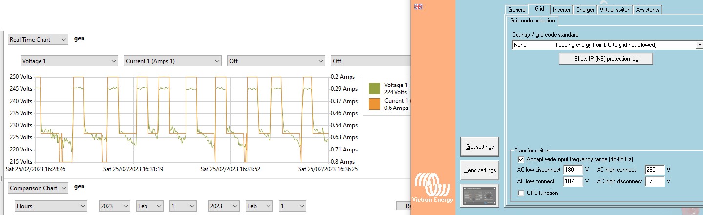
This shows that the generator is drooping to about 220v even with a very light load, but is 245v off load. However, as can also be seen, the inverter disconnect voltage is 180v BUT the generator NEVER dips this low.
So why is the inverter disconnecting with the voltage still within the permitted window?
one possible reason for the increase in open circuit voltage could be the 2.2uF capacitor wired L/N inside the Multiplus - These capacitors are on all of the AC input and outputs - apparently for emc suppression. However, the capacitative load is likely to upset some AVR generators, taking them out of the expected operating area for power factor.
I've finally solved this riddle.
After acquiring an insulation tester, and testing the generator windings with the AVR removed, I found that both the Main winding and the Excitation winding were 20MOhm to ground at 500V. However the rotor Field winding was short to ground (<10k Ohms). This had tested open at a lower voltage. This means that any ground current flowing in the external load circuit will upset the regulation of the AVR.
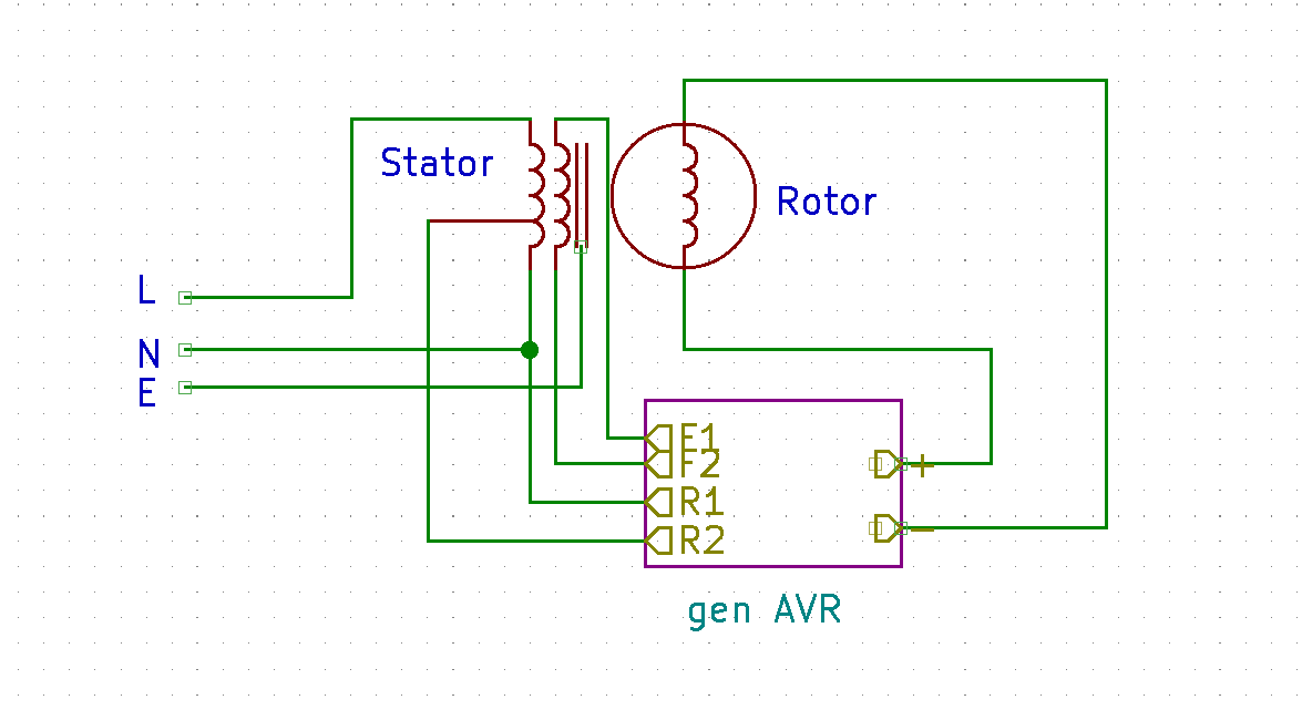 The Excitation winding provides about 40v rms, but the reference voltage is taken from a tap on the main winding. I'm not sure of the exact position of the tap, or the ratio, but the AVR switches at about 17V input. (I have a spare AVR that has been reverse engineered....). Measuring the volts to ground from the Main winding, with the generator running at 235v, gave ~50V for N-G, and ~250V for L-G. Hence any capacitive load between either N-G or L-G (more significant) will produce current flowing in the ground fault to the rotor, and thence to the AVR. These capacitances are in emc filters, cables etc. and cannot be negated.
AVR Circuit:
A spare AVR was stripped to evaluate the circuit, and to test the regulation performance.

The switching voltage as previously mentioned was approximately 17V. The change in input voltage required to turn off the FET was measured at 4mV. In terms of DC regulation, this is 0.02%, which should give very good regulation. However, Earth leakage currents will be rectified by the bridge rectifier, causing both a shift in the switching voltage in the FET, stray DC currents in the field winding, and ultimately the destruction of the AVR circuit if the ground currents are high enough - as in a Neutral - Earth link. Physical examination of the Rotor showed no visible damage, and given the potential for conductive dust build up around the slip rings, it was decided that an isolated AVR should be used (as is done in larger generator controllers) rather than seeing if a rewind would solve the problem. Addition of a few simple components to the existing AVR circuit will achieve this as shown below:-
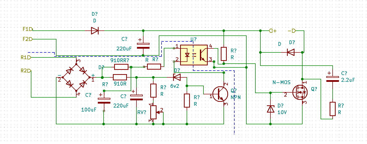
Note: Only some component values are shown.
The addition of an opto isolator in the gate drive circuit of the switching FET was the obvious start, with the provision of a supply for the opto's LED. the original gate switching transistor was retained to switch the LED. Some hacking of the pcb tracks was required to achieve the isolation barrier (dotted BLUE line). The inclusion of the series resistor in the bridge to 100uF capacitor is to prevent distortion of the sine wave - thus maintaining the regulation.
****************************************************
DISCLAIMER - Don't try this at home, unless you are 1) certain what you are doing and 2) willing to accept the consequences.
No liability will be accepted for any reason whatsoever.
*********************************************************************
Having said that, the generator was reassembled and bench tested. Main output was reset to 235v, and N-G and L-G voltages were both measured at about 80V AC, showing that isolation had been achieved. The gen was then tested with an angle grinder, and the voltage measured, showing fair regulation. The unit was then successfully tested with a spare inverter, the inverter switched into charge mode, where as before, it would immediately switch back to invert mode.
Main lesson learnt from this was that in cases where the reason for the generator not connecting is not readily apparent, it is well worth checking the ground isolation of the set -with all due care!!!