Hello from Sweden
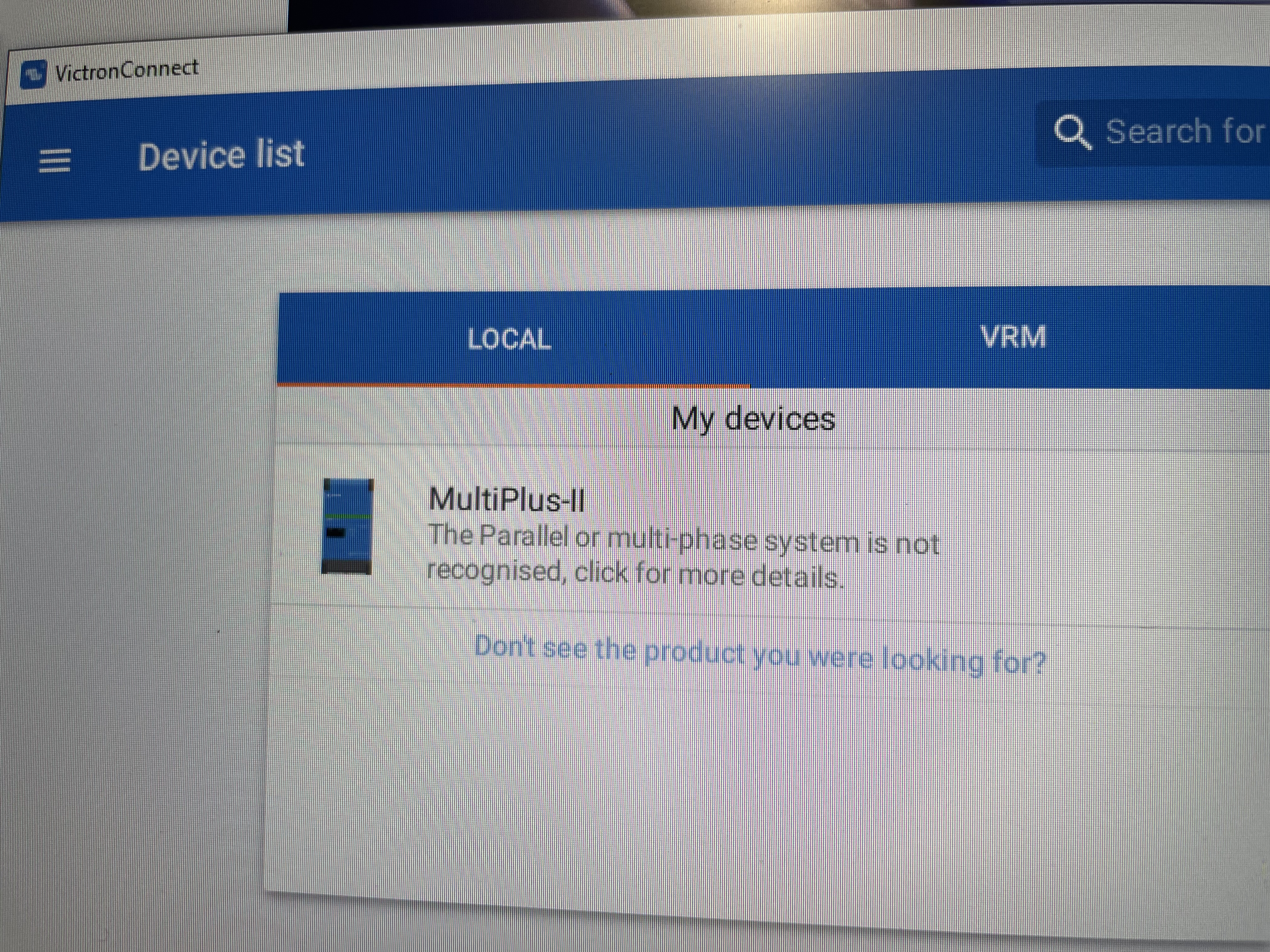
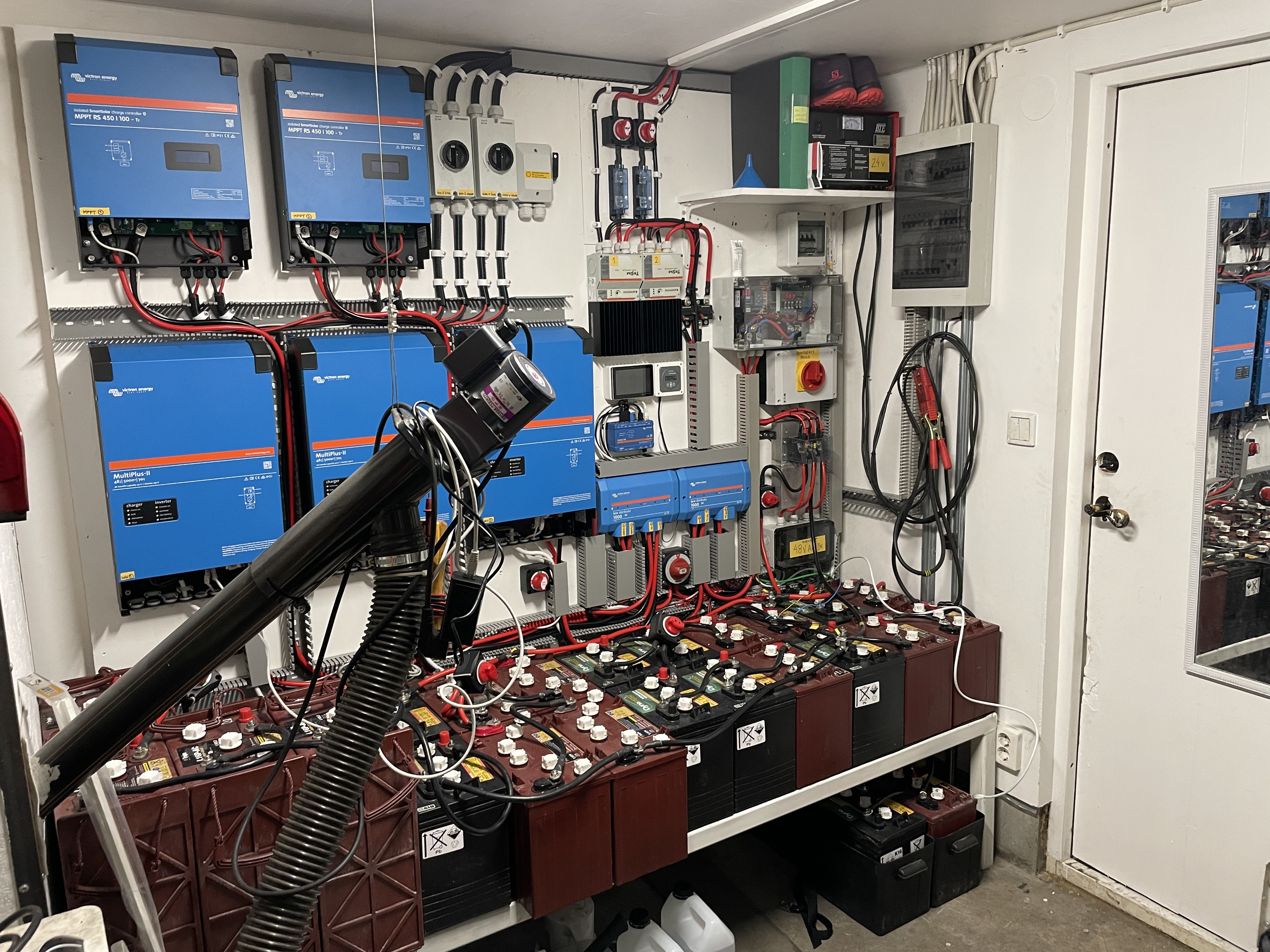
I’m Daniel and have installed a three phase ESS system at VRM ID: 48e7da8858fb May I ask @Guy Stewart (Victron Community Manager) to have a look of what I might have missed out on?
I have two issues:
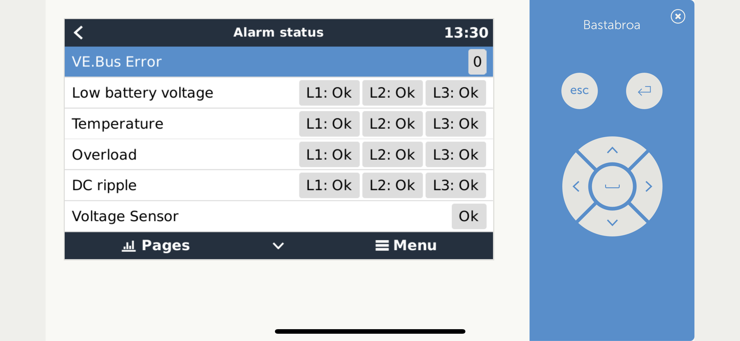
1. With the manual flick switches (one on each inverter) at the outside bottom RH of the multiplusses in ”charger only” mode, the pass through works so I can currently feed the house (-5c outside doesn’t gove room for too much downtime) but the relay test is in pending satte even though battery is fully charged.
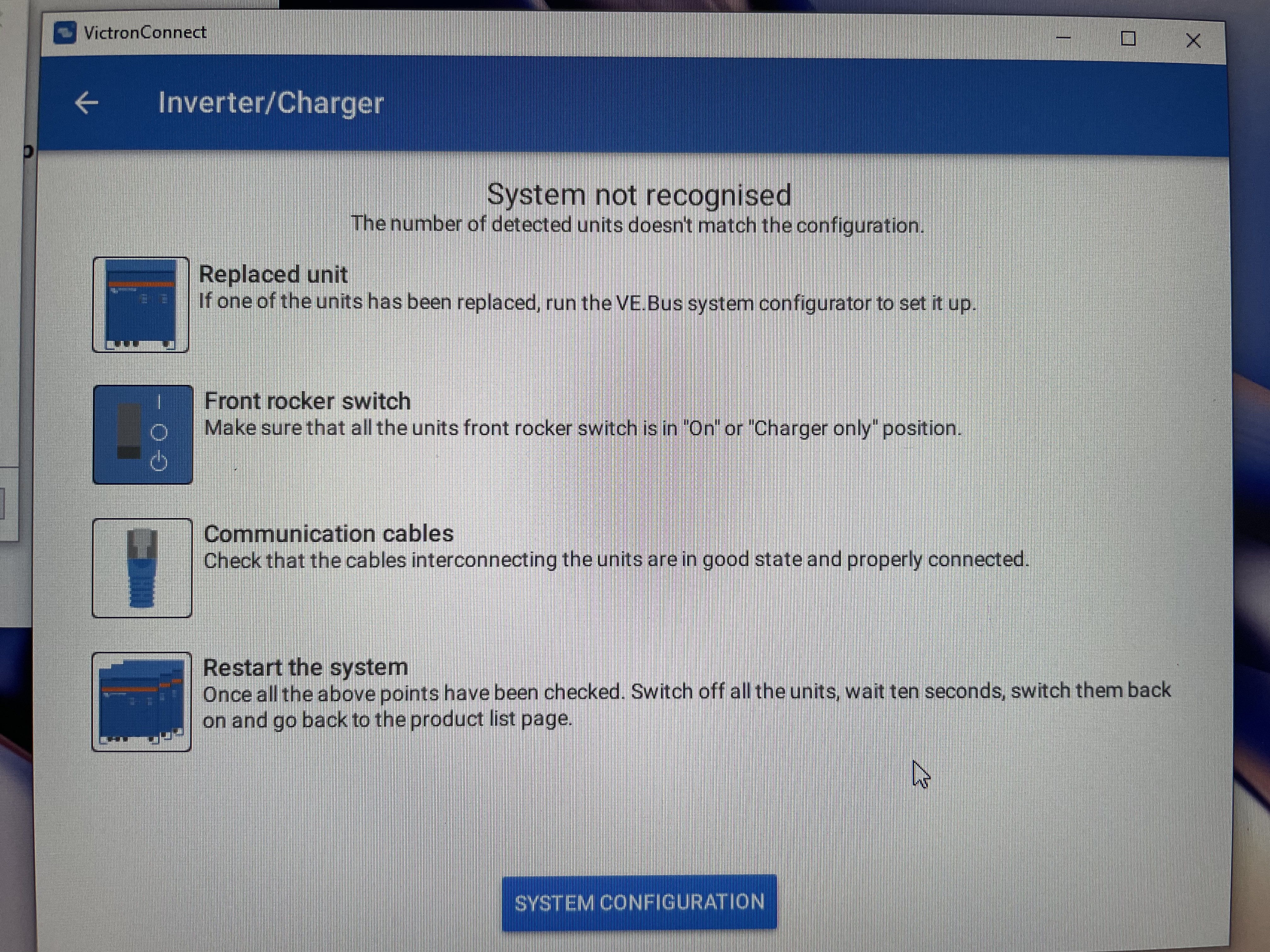
2. When I flick the 3 switches mentioned before over to ”inverter mode” the system make attempts to start up but does not succeed. I reloaded the ess assistants today and restarted but no difference. In this case, during the start up attempts i can see in the CerboGX Display menu that the relay test is completed.
Best regards
Daniel Cronblad
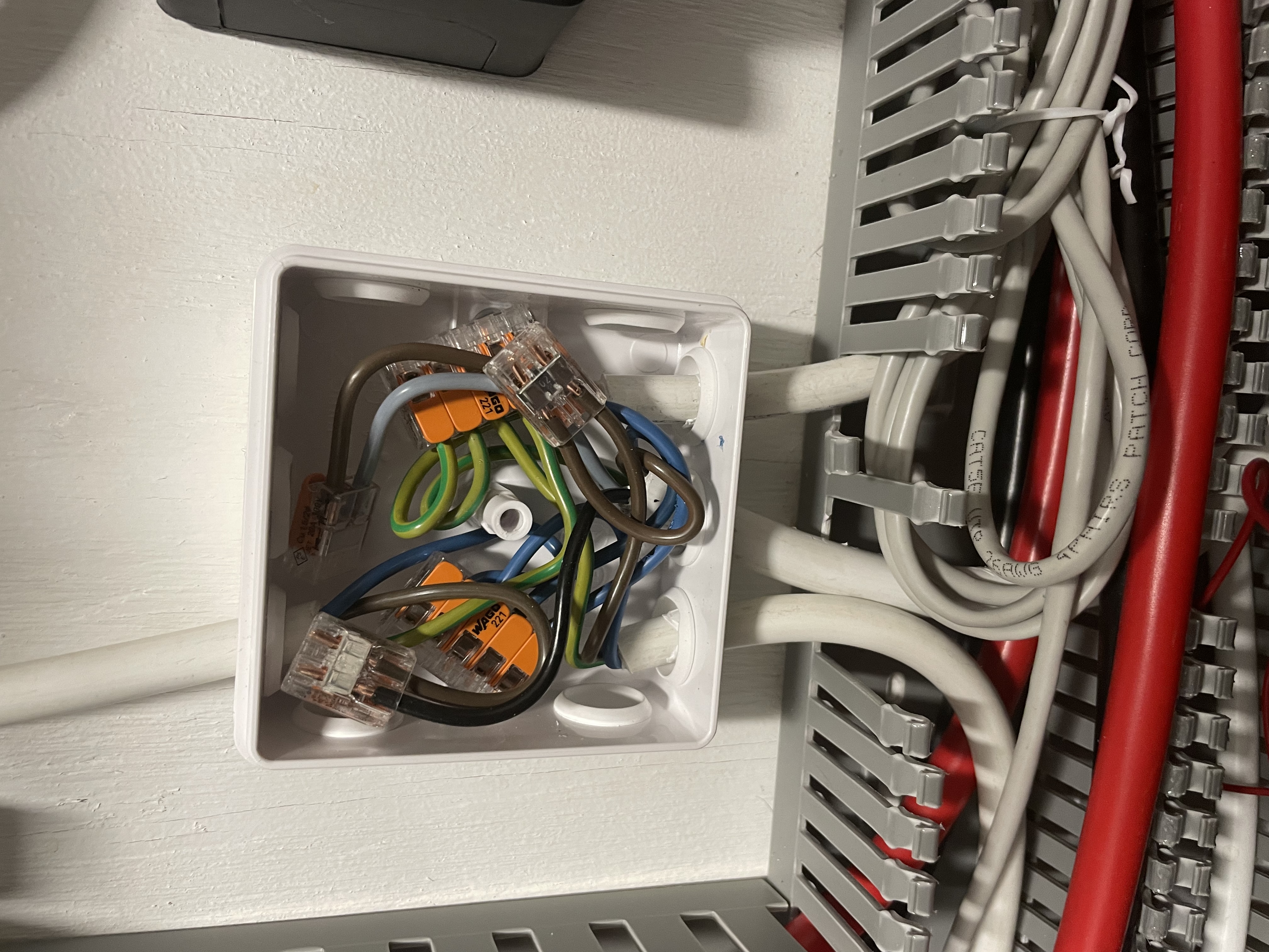
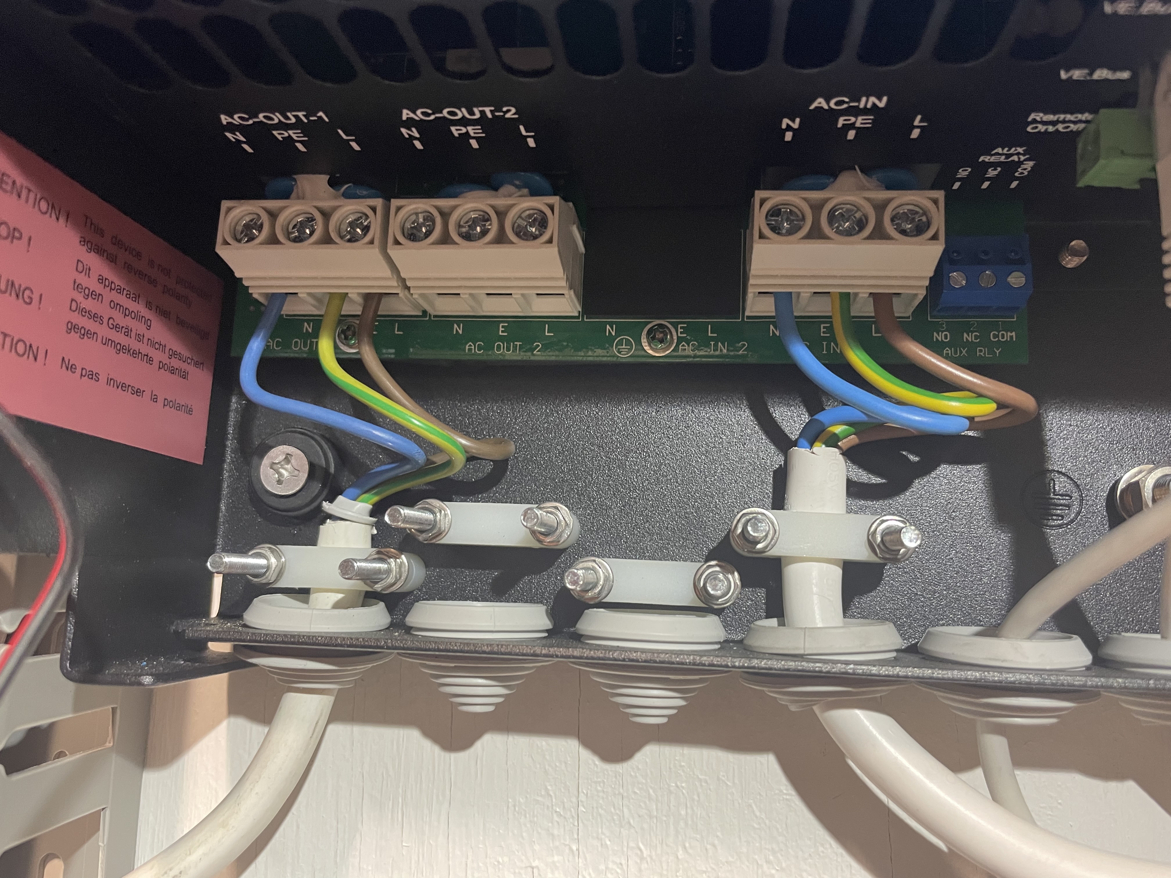
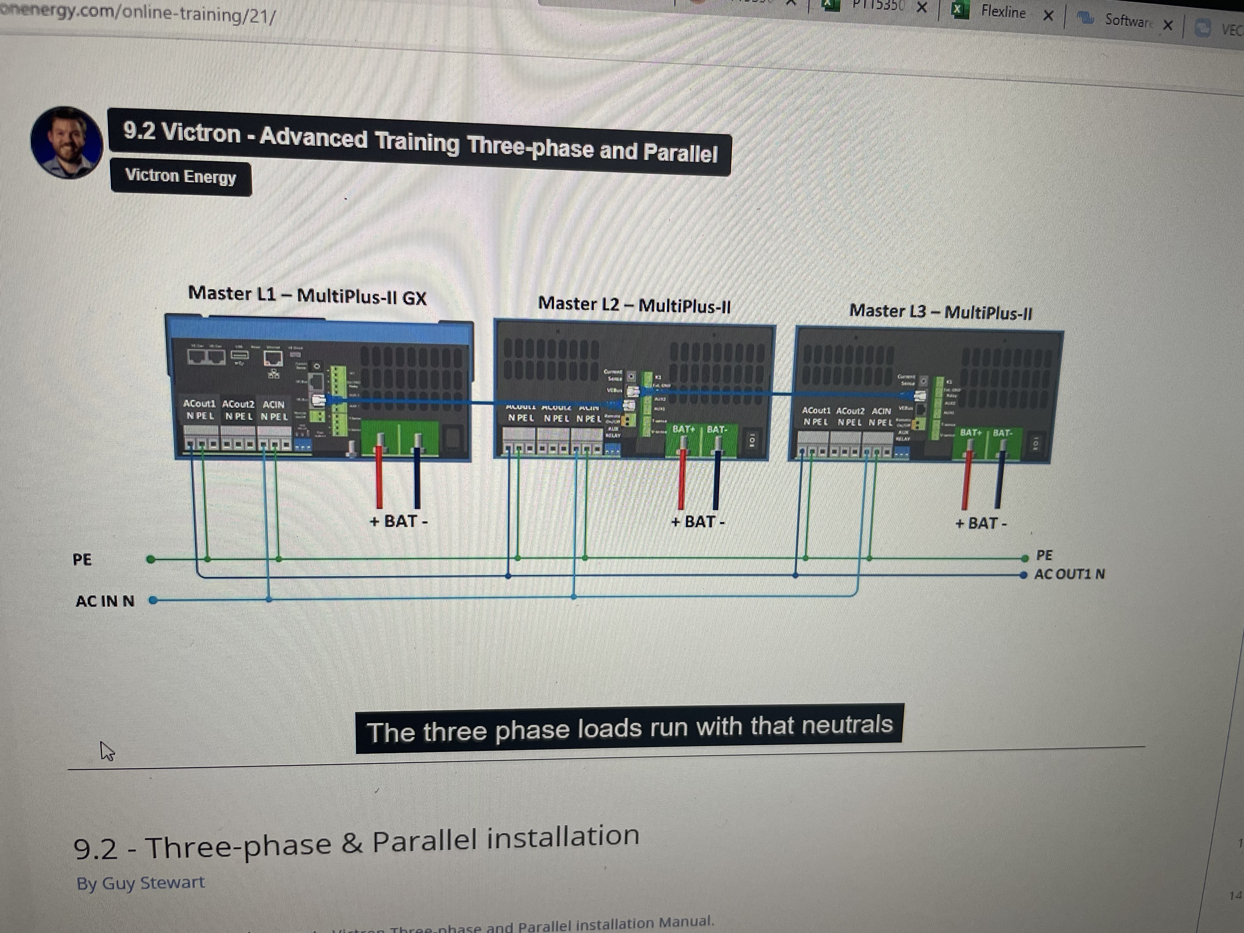 the manual states that ac out needs a common neutral for proper voltage reference. The phases I disconnected but no success unfortunately.
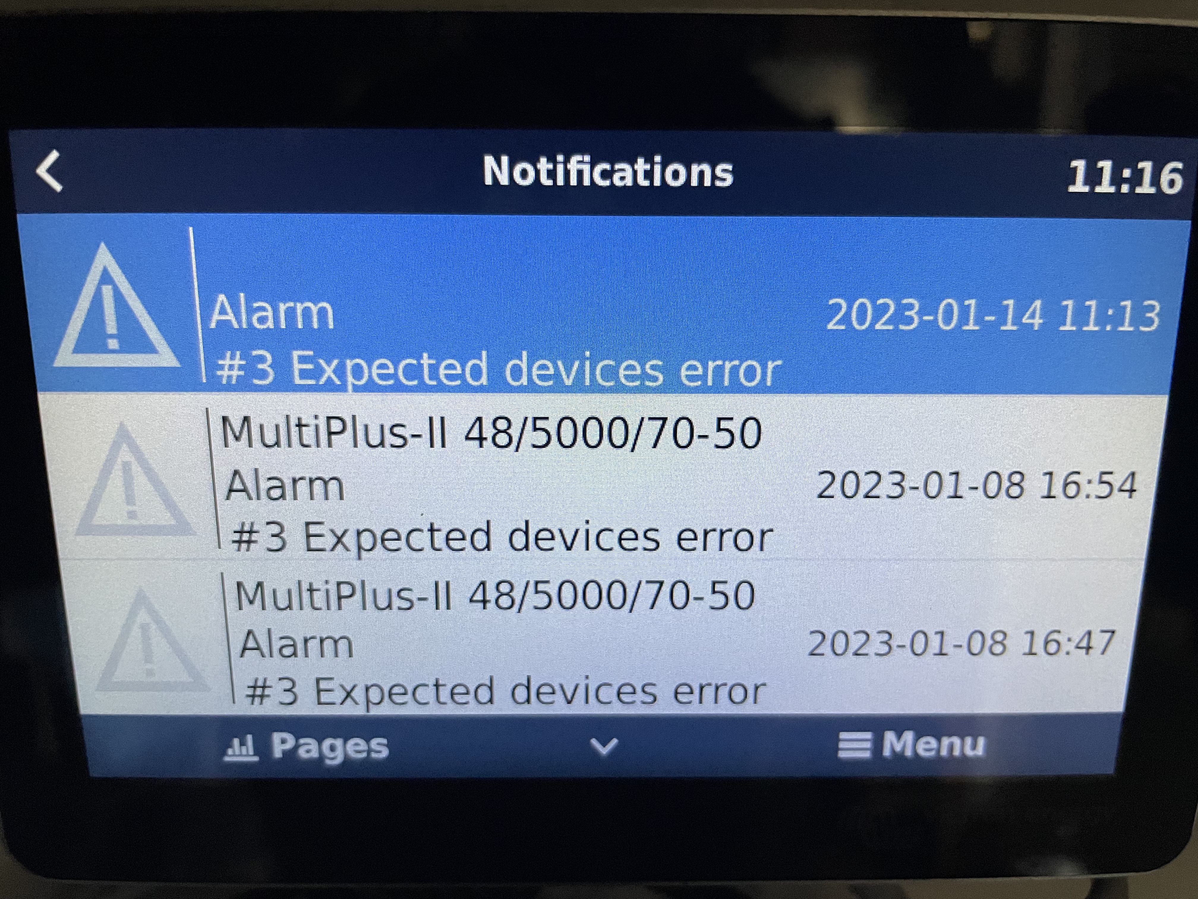
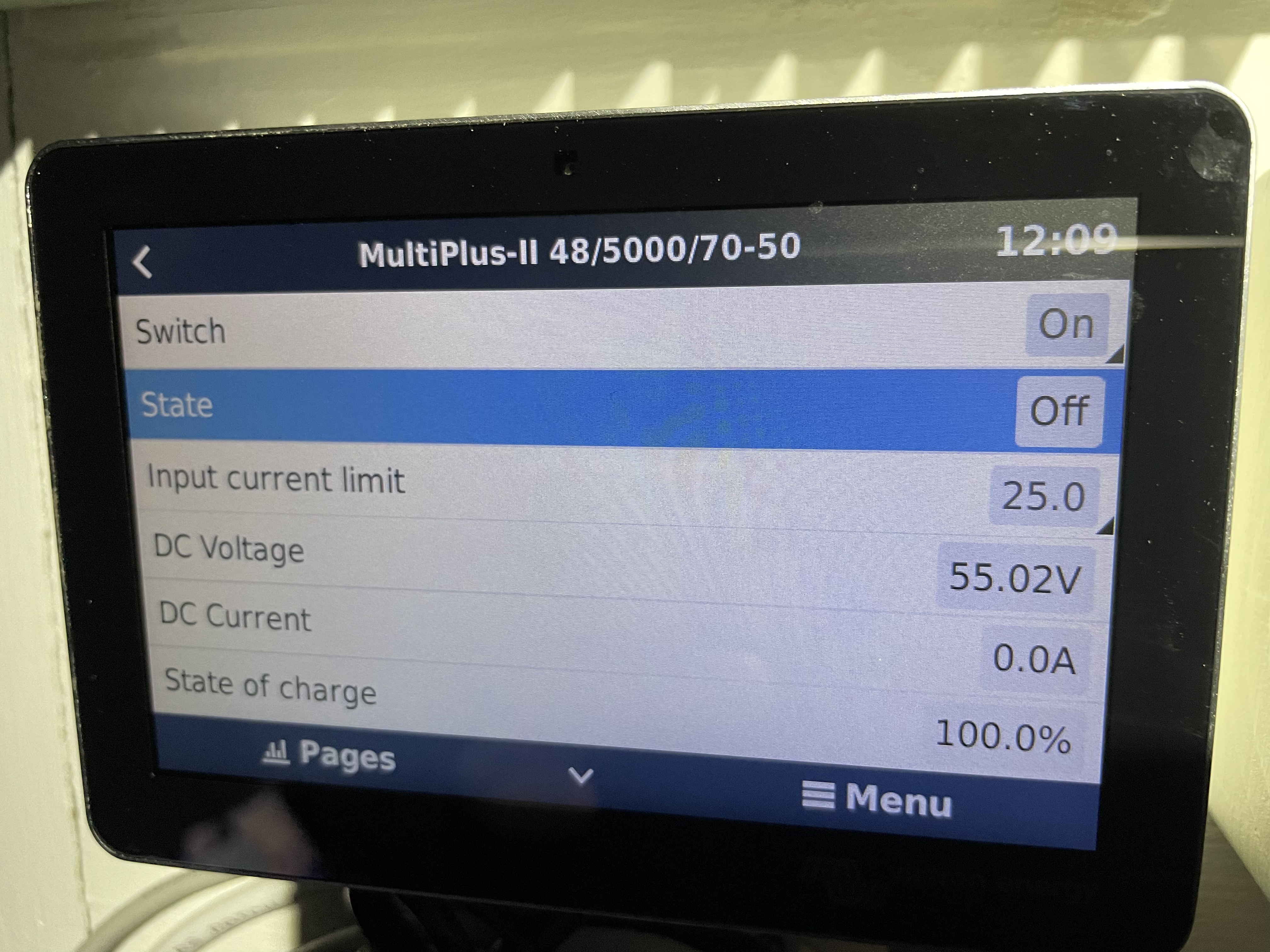 Off and fault
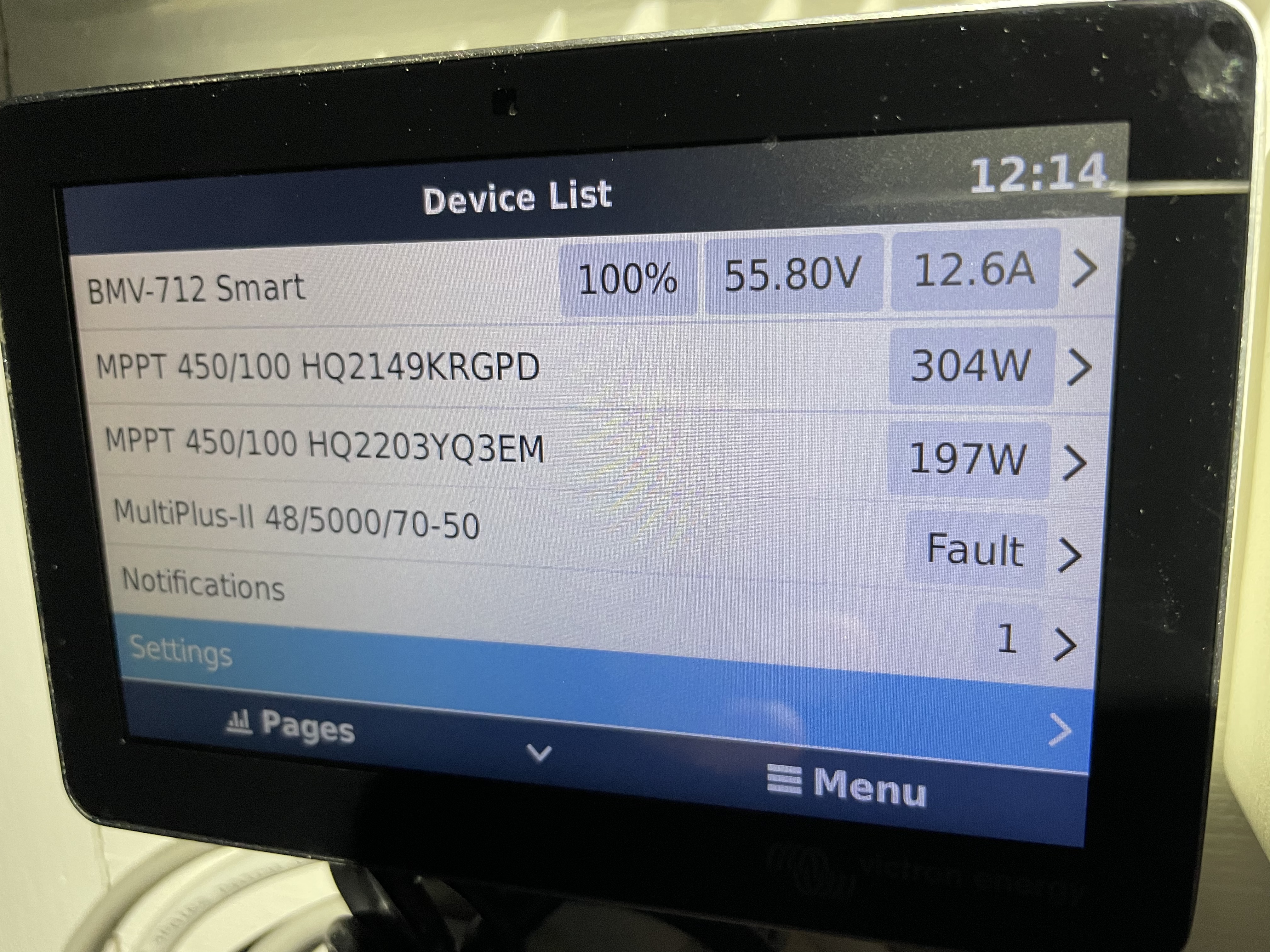
 @Alexandra