Hello friends .. some help please.
Multiplus II 24V 230V. with current sensor installed on grid input and all non critical loads connected upstream and not on AC2 out. Critical loads on AC1 as usual
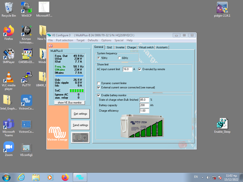
I Have checked in VEconfigure the famous external current sensor tick.
and the UPS function ticked.
and batteries are fully charged.
Now lets say i have a total of 8A input from the grid with around 2A critical and 6A non critical.
I get the strange flow meter indications AC in 8A , ACout 7.8
Should this be ACin 8A and ACout 2A?
What am i missing?
Is it some detail i missed or some bug?
Thank you.
asked
Multiplus II AC current flow meter
When you have an external CT you are basically moving were the inverter believes it is connected.
Current through CT is AC_IN and everything else is AC_OUT even tho it is not connected to the AC_OUPUT the inverter thinks it is.
The AC Out valves are calculated and not measured.
AC_OUT = AC_IN + Inverter_Power.
This is completely Normal. If you want the inverter output and input loads to show up separately then you need to install a grid meter.
@sgrigos Do you have a screenshot of the info? Is it on VRM?
Thanks Jason for replying.
No VRM, it is a local standalone inverter . I am using the MKIII and VEconfigure on an old PC with windows 7.I have yet to update the firmware because VictronConnect does not load any fonts (which i read is a rare problem with some video adapters)
I ll visit the site again tomorrow with another laptop and post a screenshot with some loads and get your advice before proceeding to firmware update.
.So here it is the vacuum cleaner on grid upstream (not ACout2)
and freezers and computer on ACout1
The current sensor is on grid input of the whole installation
Firmware is 481
Very strange . Is it supposed to meter this way?
I post another pic of the same data in victron connect