Hello- I am interested if there anything else here that I am missing or should be including? Planning to build the DC portion now, and then add more panels, batteries and AC later. Thanks in advance.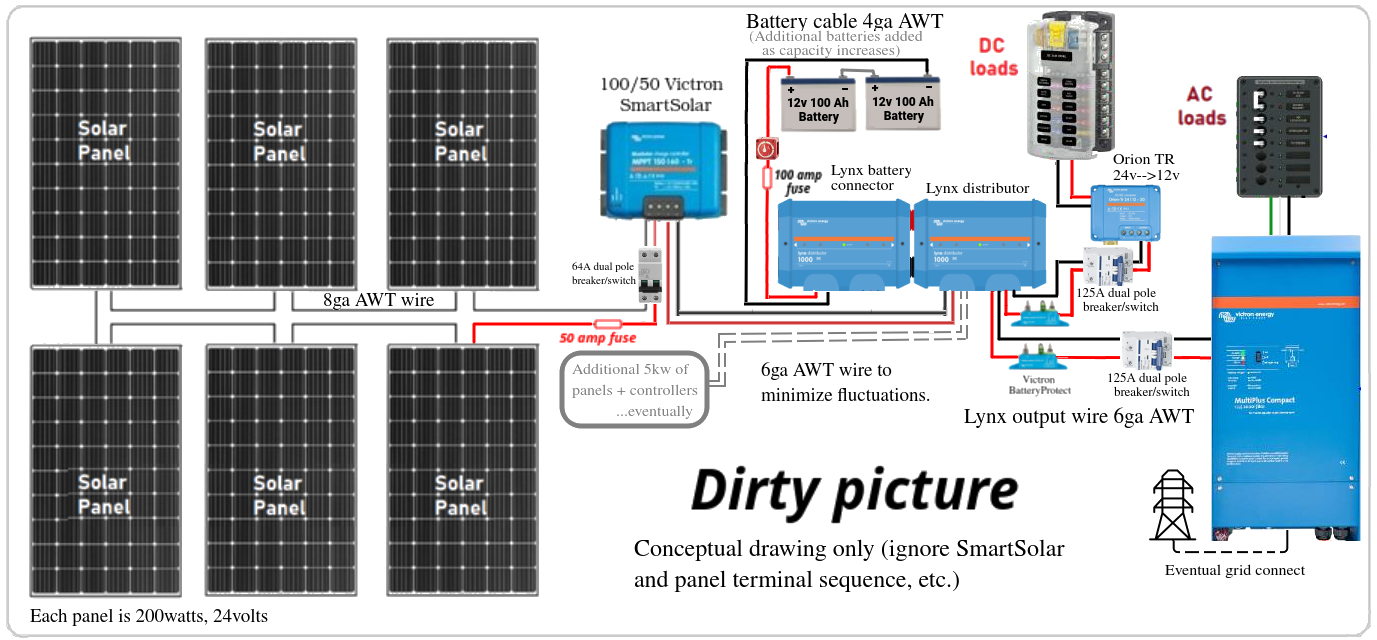
asked
Far north solar array: starting small. Planning to grid link eventually. What am I missing?
Battery Protect's are one way devices.They can not handle current flowing both to and from the battery.
Battery Protect's dont like the connection surge that inverters can subject them to. Use the low battery cutout feature in the inverter instead (or utilize the remote feature of the inverter) .
You wont find smaller than 80a mega fuses for the Lynx.
For wire & fuse sizing I like the calculator located here https://www.explorist.life/wire-sizing-calculator/
That being said...I run 2AWG from the MPPT to the Lynx system. And I fuse it inside the Lynx box but switch it close to the MPPT.
I am running a 100% off-grid land system. To me it appears that all of your wire is undersized...some way undersized based on your drawing. And remember...fuses are to protect wire from becoming the fuse.
First of all I would ask why are you running a 12v vs 48v?
One thing to look at...put the fuse and switch close to the battery on the positive side. You don't want to switch or fuse the negative side of batteries...battery negative needs a clear uniterrupted path to the ground.
Also, I have never personally seen a fuse on the negative wire going out from the inverter.
And then...I would use a 2-pole disconnect on the PVs, one to shut down the positive, the other shuts down the negative. It's required by NEC besides being a best practice. And fusing each string in an array is always a good idea.
Looking at your PVs, if they are 200w/12v that means you have to up your voltage substantially to the MPPT to charge your battery bank efficiently. A 200w/12v PV indicates they are running at about 16.7a. But that doesn't sound right. What does the label state on the PV for Open Circuit Voltage and Short Circuit Current? If your info 200w/12v is correct, you could run all of your PVs in series...resulting in 72v @ 16.7a well withing the MPPT range. That would mean a single MPPT and you could move that savings into a larger battery bank.
So there a a lot of unknowns for your situation which then dictates the equipment, wiring, fuses, etc. Based on the drawing...you should probably talk to a local expert installer/dealer.
@AHTrimble Thanks for the excellent advice and detailled criticisms. I have decided to go to 24v as future expansions will be easier and more appropriate for a building. I will review wire sizes and breaker/switch locations per your suggestions and adjust appropriately. Thanks again. Best regards. Happy Thanksgiving.
"...First of all I would ask why are you running a 12v vs 48v?"
@AHTrimble I think that is an excellent question, especially since I'd like to keep the option open to go to a larger more traditional system where 48v appears the standard. Any reason to not wire pairs of my 24v 200w panels in series, then parallel the 3 resulting 48v pairs together? Wiring size would need to change, I'd need more batteries, a different 12v transformer, and I might want to downsize the controller. Thanks in advance for your thoughts and ideas.
@portsample Please stop editing your initial post, 15 edits in and most people have no access to previous designs. Please post further changes as a comment.
You still cannot use a battery protect on an inverter. It is forbidden to use a battery protect with an inverter/charger. SBP manual.
Post a list of system components plz.
@klim8skeptic (6) Rich 200w 24v panels
(1) Victron 150v/60A SmartSolar controller
(2) Victron BatteryProtect 100A
(1) VictronLvnx 1000 Power-in
(1) VictronLvnx 1000 distributor
(1) Victron Orion-Tr Smart 12/12-30
@portsample you forgot the inverter/charger.
Rich 200w 24v panels Just be aware there are 2 different models of the 200w panel. The 12v (24.3 Voc) panel is ok for 3 in series. The 24v (45.4 Voc) panel is likely to be above the mppt's PV voltage input limit at temperature approaching freezing point. Not suitable for 3 panels in series. The panel spec sheet appears to have errors in it. Doesn't inspire confidence.
VictronLvnx 1000 distributor If you dont need the extra features of the VLD (blown led indicators/coms to other Lynx devices) You can fit fuses to a Lynx Power in. Look on Youtube for details.
Thanks for the information. I am planning to expand this into a larger system as money and time allows. That is why some of the components may seem like overkill.
Updated per comments. Approx 25-30 feet from controller to panels. Widget here https://www.explorist.life/wire-sizing-calculator/ recommends 6ga for 50A 24v over this distance with <3% voltage drop. This seems like overkill...
6ga for 50A 24v over this distance with <3% voltage drop. This seems like overkill...
It is a bit. With 6 panels paralleled @ with Isc of 5.83a, the cabling only needs to handle 35a. 6mm solar cable will handle that.
3 big problems with 6 paralleled panels will be fusing (required when paralleling more then 2 panels) each panel pos/neg lead.
Physically joining the 12 panel wires, to the 2 wires going to the mppt will be a mess. Your gunna have to get creative.
Solar MC4 connecters are only rated to 30a.
So, how do you intend to set up your PV array? Series? Parallel? Series x parallel??
Best to have a look at Wiring Unlimited page 43 regarding solar arrays.
I am beginning to see the advantages of a 48v system. Wire size. Future expansion. Access to larger household panels.
@klim8skeptic , @AHTrimble This 48V 25A 1200W design has come along way over the last month, thanks in large part to feedback from this group. I am still doing research on the inverter and will not be buying one right off. Is there anything here that I am going to regret or wish I had done different? Thanks in advance.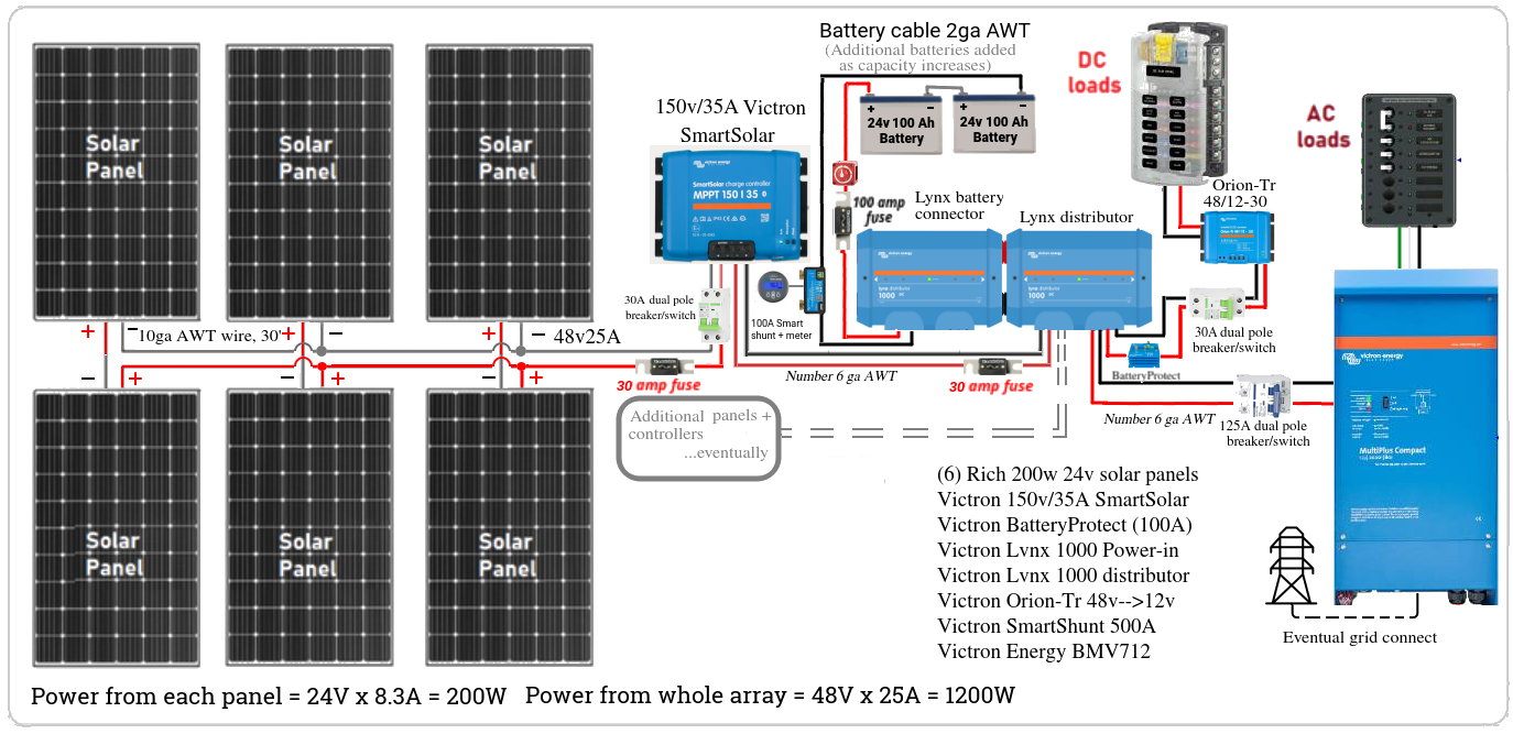
You're mixing panel and battery voltage. As long as voltage (VOC) from panels into the MPPT is 5V over the actual battery voltage, you can treat the two separately.
You can make things simpler/easier by two strings of three panels. This will run each string around 60V, but at the current of a single panel. These strings can be brought together at the MPPT. Or at the panels.
Make sure the MPPT you finally select can handle a 48V battery bank if you go that way.
In lower illumination conditions, increasing voltage into the MPPT will give longer charging time. But beware of safety issues as well as regulations about who can install higher voltage.
@kevgermany I'm confused. Output for the 3P2S system is 48v25A. I was under the impression that I would therefore need a 48v battery bank for this. If I go to 2P3S, then won't I need to increase the size of my battery bank to 60v? The specifications for the 150/45 shows battery voltages of 12/24/48v (or 36v w/software modification)...no 60v listed. I had assumed that overall system voltages needed to be at one of these levels. If this is not the case what are these levels?
The MPPT is a very sophisticated panel manager, voltage converter and charger.
About all the MPPT can't do is work with panel voltages that are too low when compared to the battery voltage. Most, if not all, Victron MPPTs will start charging once there's enough light to make panel voltage 5V higher than actual battery voltage and will continue to charge until panel voltage is less than 1V higher than battery voltage.
Hence my comment about treating the panel and battery voltages separately.
By the way 24V panels don't output 24V. It's a nominal rating. You need to check the panel specifications for actual figures. Best get the specs for the panels into the online Victron calculator, try the 2p3s and the 3p2s configurations.
Really? I had thought that your 150v panel -->12v batteries example was not an option. Clearly panels produce a range of voltages depending on cloud cover, latitude, season, etc, with the rated voltage just a general average (or midpoint). My impression was that this was also the target for most peoples systems.
Really.
In the Victron range, the input voltage and output current are part of the model name. So a 150/50 will take max input of 150V, and charge a battery at up to 50A. Victron only support battery voltages of 12/24V and on some models 48V.
Suggest you check the datasheets of the MPPTs. You can download from victronenergy.com. Go to the products, pick an MPPT and download from that page.
Solar panels produce voltage with relatively little current. Solar controllers convert this to battery voltage at much higher current.
There's a good reason for running panels at high voltages - easier and cheaper cabling with significantly lower power losses. The downside is that higher voltages are dangerous and must be professionally installed/maintained. If you check panel specifications, most are rated for 1000V systems.
Roger on all that.Three series, two parallel with my 200w 24v 8.3A panels works out to 72V at 16.6A. This make sense w/regards to low light condition generation.
What are the actual panel specs.? What you have just quoted does not match either of the 2 panels I mentioned earlier.
Panels are wired together and in place. They are Rich Solar panels 24v 8.3A 200w. Here is the Amazon link: https://www.amazon.com/RICH-SOLAR-Moncrystalline-Solar-Panel/dp/B086WYLCRM/?th=1
Curiously, the panels are putting out approximately 45 volts each: nearly double of what I anticipated. I have six panels total. They are set up as 2 parallel banks of 3 panels. Voltage from each bank of three is 140 volts. It is a sunny day, ambient temp is 40 degrees F and the panels are warm to the touch in direct sun. I had assumed that output would be in the neighborhood of 72 volts. With this in mind, I purchased a Victron 150v/35A Smart Solar controller. Now instead of being at half of the controller's rated capacity, I am at 93% of it. Interested in the group's thoughts on this. What is considered to be a reasonable margin for these units? Thanks in advance.
@portsample Curiously, the panels are putting out approximately 45 volts each: nearly double of what I anticipated.
That matches the Rich 200w datasheet that I linked to on 25 November.
Voltage from each bank of three is 140 volts. It is a sunny day, ambient temp is 40 degrees F
You had better rewire your array as 2 series x 3 parallel, before the smoke escapes from the mppt, and it stops working forever.
Thanks for the response. Never wired the 150v controller in. I'll be installing a 250v/60a unit.