question

Tom Ranson avatar image
Tom Ranson asked

Top section voltage spikes, huge jump in mid-point deviation

Hi all,


My setup:

- 8x Leoch DT126 6V 240Ah in serial/parallel for 24V 480Ah (with HA02 energy transfer battery equalisers on each series string)

- SmartShunt 500A

- 2x MPPT 100/30

- Cerbo GX


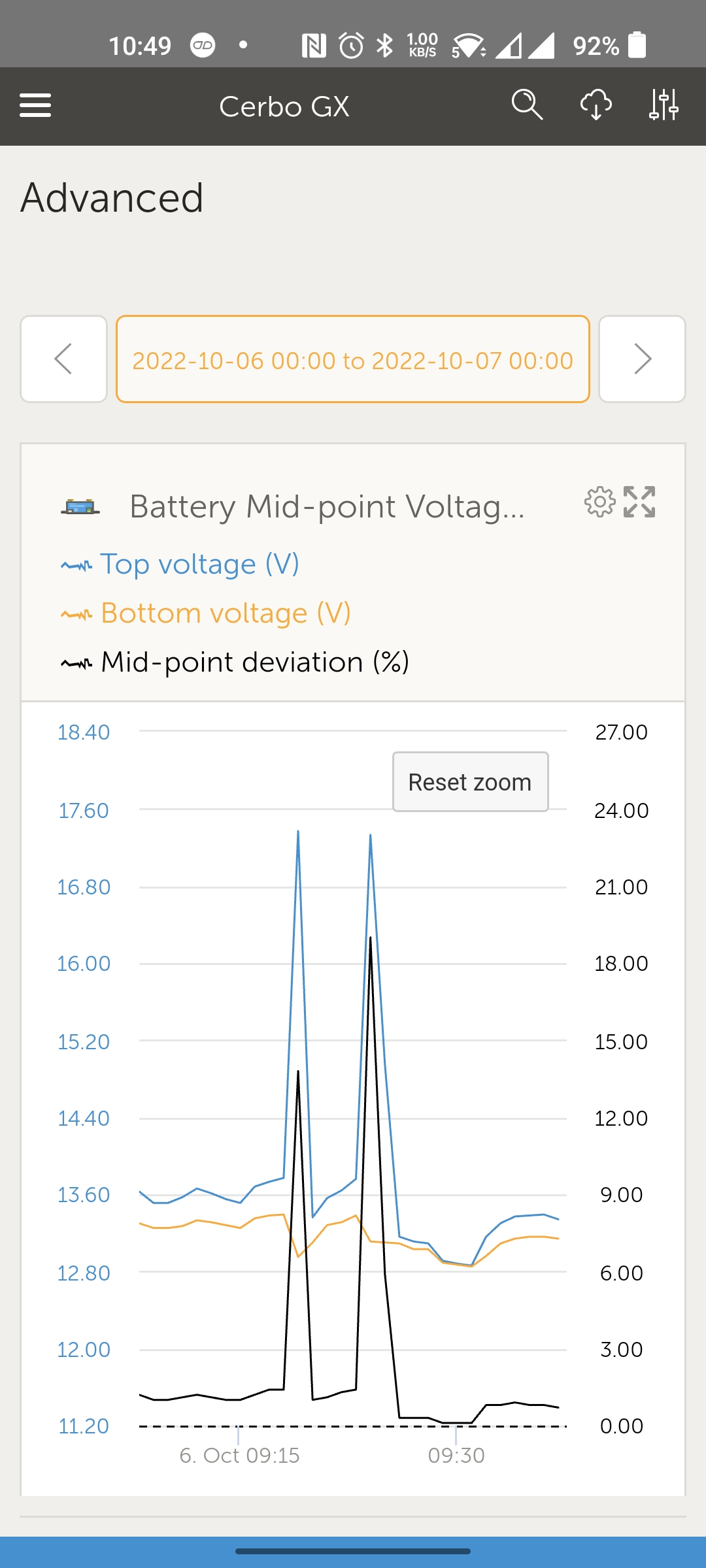
I am seeing very high top section voltage spikes (around 17V) during periods of more intense sun (therefore higher charge currents). This leads to sudden very large mid-point deviations (around 15-20%), which results in a mid-point deviation alarm (threshold 2.0%) and the Cerbo GX cutting off the MPPT charge current temporarily, during which time the top section voltage drops and the mid-point alarm clears. This pattern then repeats every 30 or so seconds.


This is best explained by a screenshot from VRM. As you can see, the bottom section voltage is steady, but the top is spiking very high.


screenshot-2022-10-09-10-49-27-82-bc2aea2f1887607a.jpg


I first noticed this issue when both MPPT's were online at the same time, therefore generating twice the charge current of one. If I disable one of the MPPT's, then I do not see the spikes. Presumably this is due to the charge currents being lower.

To avoid the issue for now, I have reduced the maximum charge current of both MPPT's to 10A each, therefore maximum potential charge current of 20A, however obviously this limits my charging capacity. Previously I was seeing charge currents of 20+ Amps and then the voltage spikes would manifest.

What am I missing here? Why I am seeing these top section voltage spikes? They are clearly "not right" and I worry if I left the setup in this way I would damage my batteries. Is my charge current too high? If I base maximum charge current on 10% of the C20 battery bank capacity then I should be looking at about 48A as an appropriate charge current.


Here's a link to my system schematic https://1drv.ms/b/s!AqotUnsPzM2bsjg9ka0I5fuoRy6S

Standing by to provide further information. Many thanks as always.

MPPT Controllersvoltage
2 |3000

Up to 8 attachments (including images) can be used with a maximum of 190.8 MiB each and 286.6 MiB total.

3 Answers
Trevor Bird avatar image
Trevor Bird answered ·

@Tom Ranson … Tom, having another look at the drawing suggests the problem is associated with the 10mm cable from the battery, the 60amp fuse or the cabling from the fuse to the junction of the take off point for the smart shunt voltage sense. This makes sense as for the batteries to have a problem, two simultaneous faults would have to occur. Very unlikely.

The 60 amp fuse is faulty or the fuse holder is not good or the connections are not good. If that occurs the multiplus and batteries would perform ok but when charging the circuit from MPPT controllers the voltage would spike when the charge circuit went open circuit. Mid point voltage would remain ok because that is measuring actual battery terminal voltage. Please check the wiring to and from the 60 amp fuse.

15 comments
2 |3000

Up to 8 attachments (including images) can be used with a maximum of 190.8 MiB each and 286.6 MiB total.

klim8skeptic avatar image klim8skeptic ♦ commented ·
Mmmm.. Dogy breakers?

OP, nice diagram.

0 Likes 0 ·
Tom Ranson avatar image Tom Ranson klim8skeptic ♦ commented ·
@klim8skeptic this certainly seems like a distinct possibility, specifically the 60A between the battery +ve busbar and the two MPPT's.
0 Likes 0 ·
Tom Ranson avatar image Tom Ranson commented ·

@Trevor Bird my answers inline in bold.

Tom, having another look at the drawing suggests the problem is associated with the 10mm cable from the battery, the 60amp fuse or the cabling from the fuse to the junction of the take off point for the smart shunt voltage sense. This makes sense as for the batteries to have a problem, two simultaneous faults would have to occur. Very unlikely.

I agree, this makes sense. The 60A fuse (breaker) seems to be the most likely culprit, thus if going open circuit, it is disconnecting the two MPPT's from the battery when the event occurs. And because the SmartShunt vbatt+ is currently connected on the MPPT side of the 60A fuse, when it goes open circuit, were seeing the top section voltage spiking, which is causing the huge midpoint deviation. Or, a dodgy termination/cable. How about I terminate both MPPT's individually directly to the +ve bus bar directly above the two battery fuses via their respective 40A fuses, and thus eliminate the 60A fuse and associated wiring?

The 60 amp fuse is faulty or the fuse holder is not good or the connections are not good. If that occurs the multiplus and batteries would perform ok but when charging the circuit from MPPT controllers the voltage would spike when the charge circuit went open circuit. Mid point voltage would remain ok because that is measuring actual battery terminal voltage. Please check the wiring to and from the 60 amp fuse.

But the mid point voltage is "also "spiking". Is this simply because the SmartShunt vbatt+ is seeing the top section voltage spike, but the bottom section remains unaffected?

0 Likes 0 ·
Tom Ranson avatar image Tom Ranson Tom Ranson commented ·

@Trevor Bird @JohnC @klim8skeptic here's an updated v0.2 schematic after moving the SmartShunt vbatt+ from the MPPT side bus bar (top right) of the 60A fuse to the battery side bus bar (top left).

https://1drv.ms/b/s!AqotUnsPzM2bsjqFiuvvFDoJL2jF

What would be your observations as to how this will effect the behaviour I will see?

In my understanding, I should now no longer see top section voltage spikes, however if the 60A fuse or associated cabling is the root cause, then I will still see the MPPT's being disconnected from the battery under high load. I will remove my current 10A charging current limit on both MPPT's and wait for some high intensity sunlight in order to see if this manifests under high current (it's predictable behaviour, under "higher" currents (not entirely certain from memory as to how high) and see if the MPPT's are reporting the charging current suddenly going to zero A, before recovering shortly there after.

If I stop seeing top and mid point voltage spikes I will be a LOT happier as I won't be worried that my batteries are going to suffer damage!

I look forward to your thoughts.


0 Likes 0 ·
Trevor Bird avatar image Trevor Bird Tom Ranson commented ·

@Tom Ranson . My answers in Italics


OK, so to be clear, I should move the SmartShunt vbatt+ to the +ve bus bar above the 2x 300A battery fuses? Please can you explain for me why this is important and why the current placement is not correct as I'm not sure I understand why. Sorry if I'm being thick.

The voltage sensing should be as close to the battery terminals as you can get it. The voltage drop across the 10mm cable may not be much but under high charging current (especially if long cable) may be a small amount enough to slightly change the sensing voltage reading. Our aim is to be accurate as possible and not be fooled by slight variations caused by voltage drop of system cables. The new drawing is much better. That is why a smart battery sense module (bluetooth to MPPTs) is connected right on the battery terminals.

Somewhere around that 60amp fuse is the problem.

Ok noted. So the SmartShunt is currently monitoring the top section voltage on the "wrong" side of the 60A fuse, and the midpoint via direct connection to the 3rd +ve terminal of one of the battery strings. So if my SmartShunt vbatt+ was connected on the main battery busbar, I likely wouldn't be seeing these big voltage spikes? But, how is the SmartShunt remaining powered if the 60A cable/fuse is going open circuit? Oh, silly me, it's being powered by the MPPT's!

Yes, correct. If you were sensing off the top of the 300 amp fuses you would not be seeing the variation in terminal voltages.

I am using resettable circuit breakers as opposed to fuses throughout, so it's a 60A breaker. Is it just possible that this is defective and only showing the issue under high(er) current?

Yes. very possible. remember you have 60 amps of charging current (2 x 30 amp) and a 60 amp breaker. Right on the limit.

The cable to the Multiplus needs to be heavy enough so reduce voltage drop under its highest current load. That depends on size of Multiplus and length of cable run.

Agreed. I've implemented 50mm2 with 300A fuses as per the recommendations. The cable runs are approx 1m.

Very good

The Wiring Unlimited booklet by Victron is a good reference to know you have the right size cable for the job. Just google that name and you can download it.

Agreed, I've reviewed this and implemented cable and fuses as per.


0 Likes 0 ·
Tom Ranson avatar image Tom Ranson Trevor Bird commented ·

@Trevor Bird my responses in bold again.

OK, so to be clear, I should move the SmartShunt vbatt+ to the +ve bus bar above the 2x 300A battery fuses? Please can you explain for me why this is important and why the current placement is not correct as I'm not sure I understand why. Sorry if I'm being thick.

The voltage sensing should be as close to the battery terminals as you can get it. The voltage drop across the 10mm cable may not be much but under high charging current (especially if long cable) may be a small amount enough to slightly change the sensing voltage reading. Our aim is to be accurate as possible and not be fooled by slight variations caused by voltage drop of system cables. The new drawing is much better. That is why a smart battery sense module (bluetooth to MPPTs) is connected right on the battery terminals.

Makes perfect sense. This was an oversight on my part, thinking more about the clarity of my wiring than the place I should have been taking the monitoring reading from... lesson learnt.

Somewhere around that 60amp fuse is the problem.

Ok noted. So the SmartShunt is currently monitoring the top section voltage on the "wrong" side of the 60A fuse, and the midpoint via direct connection to the 3rd +ve terminal of one of the battery strings. So if my SmartShunt vbatt+ was connected on the main battery busbar, I likely wouldn't be seeing these big voltage spikes? But, how is the SmartShunt remaining powered if the 60A cable/fuse is going open circuit? Oh, silly me, it's being powered by the MPPT's!

Yes, correct. If you were sensing off the top of the 300 amp fuses you would not be seeing the variation in terminal voltages.

Ok- that makes perfect sense and is now in place. I will monitor things closely on VRM, and then do some more detailled anaylsis under the "test conditions" which result in "failure" using Victron Connect graphing.

I am using resettable circuit breakers as opposed to fuses throughout, so it's a 60A breaker. Is it just possible that this is defective and only showing the issue under high(er) current?

Yes. very possible. remember you have 60 amps of charging current (2 x 30 amp) and a 60 amp breaker. Right on the limit.

Very good point. I don't believe that I have seen either MPPT pushing that much current yet- I wish I had a record of the current that was seen at the time of the "failure".

The cable to the Multiplus needs to be heavy enough so reduce voltage drop under its highest current load. That depends on size of Multiplus and length of cable run.

Agreed. I've implemented 50mm2 with 300A fuses as per the recommendations. The cable runs are approx 1m.

Very good.

Nothing more to say here :-)

The Wiring Unlimited booklet by Victron is a good reference to know you have the right size cable for the job. Just google that name and you can download it.

Agreed, I've reviewed this and implemented cable and fuses as per.

0 Likes 0 ·
Trevor Bird avatar image Trevor Bird Tom Ranson commented ·
You will no longer see the voltage variations because you will be sensing closer to the battery. If the problem is not resolved you will see charge current variations as the charging circuit intermittently goes open circuit.
0 Likes 0 ·
Tom Ranson avatar image Tom Ranson Trevor Bird commented ·
@Trevor Bird yes, makes perfect sense now. I will remove the present 10A (each) current limit set on the MPPT's and monitor for open circuit during more intensive sun to see the failure condition. I would now expect to see only charge current variations (likely going suddenly to zero amps) if I leave the MPPT's connected how they currently are (on the right of the suspect 60A fuse/cable), however it would seem better practice for me to terminate these directly onto the +ve bus bar directly above the batteries- I intend to rewire to do this, as it's better practice overall.
1 Like 1 ·
Trevor Bird avatar image Trevor Bird Tom Ranson commented ·

@Tom Ranson ..answers again again in italics

Tom, having another look at the drawing suggests the problem is associated with the 10mm cable from the battery, the 60amp fuse or the cabling from the fuse to the junction of the take off point for the smart shunt voltage sense. This makes sense as for the batteries to have a problem, two simultaneous faults would have to occur. Very unlikely.

I agree, this makes sense. The 60A fuse (breaker) seems to be the most likely culprit, thus if going open circuit, it is disconnecting the two MPPT's from the battery when the event occurs. And because the SmartShunt vbatt+ is currently connected on the MPPT side of the 60A fuse, when it goes open circuit, were seeing the top section voltage spiking, which is causing the huge midpoint deviation. Or, a dodgy termination/cable. How about I terminate both MPPT's individually directly to the +ve bus bar directly above the two battery fuses via their respective 40A fuses, and thus eliminate the 60A fuse and associated wiring?

Good idea...better design.

The 60 amp fuse is faulty or the fuse holder is not good or the connections are not good. If that occurs the multiplus and batteries would perform ok but when charging the circuit from MPPT controllers the voltage would spike when the charge circuit went open circuit. Mid point voltage would remain ok because that is measuring actual battery terminal voltage. Please check the wiring to and from the 60 amp fuse.

But the mid point voltage is "also "spiking". Is this simply because the SmartShunt vbatt+ is seeing the top section voltage spike, but the bottom section remains unaffected?

The mid point voltage is not spiking. The mid point variation is spiking in sympathy with the top section voltage sensing spiking.

0 Likes 0 ·
Tom Ranson avatar image Tom Ranson Trevor Bird commented ·

@Trevor Bird answers again in bold:

Tom, having another look at the drawing suggests the problem is associated with the 10mm cable from the battery, the 60amp fuse or the cabling from the fuse to the junction of the take off point for the smart shunt voltage sense. This makes sense as for the batteries to have a problem, two simultaneous faults would have to occur. Very unlikely.

I agree, this makes sense. The 60A fuse (breaker) seems to be the most likely culprit, thus if going open circuit, it is disconnecting the two MPPT's from the battery when the event occurs. And because the SmartShunt vbatt+ is currently connected on the MPPT side of the 60A fuse, when it goes open circuit, were seeing the top section voltage spiking, which is causing the huge midpoint deviation. Or, a dodgy termination/cable. How about I terminate both MPPT's individually directly to the +ve bus bar directly above the two battery fuses via their respective 40A fuses, and thus eliminate the 60A fuse and associated wiring?

Good idea...better design.

I will implement this change and take the suspect 60A breaker out of service.

The 60 amp fuse is faulty or the fuse holder is not good or the connections are not good. If that occurs the multiplus and batteries would perform ok but when charging the circuit from MPPT controllers the voltage would spike when the charge circuit went open circuit. Mid point voltage would remain ok because that is measuring actual battery terminal voltage. Please check the wiring to and from the 60 amp fuse.

But the mid point voltage is also "spiking". Is this simply because the SmartShunt vbatt+ is seeing the top section voltage spike, but the bottom section remains unaffected?

The mid point voltage is not spiking. The mid point variation is spiking in sympathy with the top section voltage sensing spiking.

Sorry, I didn't mean mid point voltage- I meant mid point deviation/variation %. And yes, it is spiking in sympathy of the top section voltage spike, which hopefully we will no longer see.

0 Likes 0 ·
Trevor Bird avatar image Trevor Bird Tom Ranson commented ·
Great...let's know how you get on.
0 Likes 0 ·
Tom Ranson avatar image Tom Ranson Trevor Bird commented ·

@Trevor Bird @JohnC @klim8skeptic Hi everyone, so I've completed the rewire and the system now looks like in this v0.3 schematic. The 60A breaker has been removed entirely.

Ivy Cottage Victron schematics v0.3.pdf

I am suspicious of the 60A breaker which has been removed as upon closer examination it appears to be of a slightly different design and of inferior quality to all of the other varying amperage ones I am using/have on hand.

There have been no issues with the top section voltage or mid point deviation these last couple of days (since moving the SmartShunt vbatt+ to the +ve bus bar, however I have only completed the other aspects of the rewire today, so it's too soon to say, however I am hopeful given all we have discussed.

Finally, I have removed the 10A limits on both MPPT's and returned these to their 30A ratings. Both MPPT's are now online. Unfortunately at the moment sunshine is scarce so I haven't seen any high(er) current generation yet.


I look forward to hearing your thoughts.

0 Likes 0 ·
Trevor Bird avatar image Trevor Bird Tom Ranson commented ·
@Tom Ranson ..Well done..I think you have resolved it.
0 Likes 0 ·
Tom Ranson avatar image Tom Ranson Trevor Bird commented ·
Yep, looks like we're all good now. I'll mark your original answer re. the 60A fuse as accepted! Many thanks indeed.
0 Likes 0 ·
klim8skeptic avatar image klim8skeptic ♦ Tom Ranson commented ·
Eagerly

awaiting

an

outcome

.

:)

0 Likes 0 ·
Trevor Bird avatar image
Trevor Bird answered ·

@Tom Ranson it looks like one of the batteries or a connection in each of the upper strings is failing. No Fault in the MPPT controller could cause this because the battery terminal voltage would be maintained under all reasonable circumstances. Please ensure you have VERY tight terminals on the connections between the batteries in the upper string of both strings. You could separate the strings and try this experiment on one string at a time. Put a meter across each battery in the string and see what happens to the terminal voltage on each battery. One of them in each string is either failing or a connection is high resistance. It would be very unusual for two strings to have a failed connection or a failed battery at exactly the same time. My guess is one is permanantly failed and the other string has a connection failure or a battery failure. This will be a battery or installation issue. Methodically work through this problem. FIrstly separate the strings and just concentrate of one of them. When you find the issue (Faulty connection or faulty battery) move to the other string. Find the problem with the other string. Only when you have resolved both strings, join them back together.

I hope this helps.

1 comment
2 |3000

Up to 8 attachments (including images) can be used with a maximum of 190.8 MiB each and 286.6 MiB total.

Tom Ranson avatar image Tom Ranson commented ·

@Trevor Bird many thanks for your detailed response.


Due to this problem, I recently took the whole system offline to individually charge and test each battery. Each battery went on a 6A charger until it was fully charged and holding voltage. I then left all of the batteries disconnected for 48 hours to let voltages settle down and to keep an eye on their end voltages and they all settled at approx 6.40V (6.39-6.42). Is this conclusive enough to confirm that the batteries are all in acceptable condition, or do I need to also measure specific gravities too? The batteries are all less than 3 months old from new.

So would this suggest more that it is a cabling issue? Or am I over simplifying things? How should I go about testing eliminating this aspect please? The battery link wires and those to the bus bars are all 50mm2.

Here is a copy of my schematic (albeit ommiting the new HA02 battery equalisers)- can you spot anything that I've potentially done wrong? Ivy Cottage Victron schematics v0.1.pdf

0 Likes 0 ·
Trevor Bird avatar image
Trevor Bird answered ·

@Tom Ranson I think the circuit looks good. If the batteries are fairly new it is very unlikely it is a battery problem. Batteries are a device with a fairly low internal resistance. What that means is the voltage of the battery will be maintained if the current is low or high. The MPPT controllers would not have the ability to provide enough current to really change the terminal voltage of those batteries as displayed in the VRM. They may change it a little but nothing like that change as seen in the VRM. That means the only other thing that can be happening is the connections between the batteries is failing (high resistance) or one of the batteries in each upper string is failing (most unlikely). The confusing part of this is the failure would normally be evident when the Multiplus is drawing heavy current. Let's just handle what we can see and troubleshoot that and methodically track this down. If we assume the batteries are ok, the only explanation is one of the connections in EACH upper string is intermittently failing. I know this may seem unlikely but no other reasonable explanation remains. Separate the strings and treat them one at a time. I say this because with two strings in parallel, each string must have a problem to exhibit this fault. I know that is very strange so treating each string one at a time allows each problem to be identified. Perhaps allow the MPPT controllers to feed maximum current to the batteries to make it fail. Now check with a meter each battery and this may reveal where the interconnecting cable has failed (or very unlikely the failed battery).

Just troubleshoot one string at time and you will find the problem. It can only be a very small number of things so good luck and keep us informed of what you find.

5 comments
2 |3000

Up to 8 attachments (including images) can be used with a maximum of 190.8 MiB each and 286.6 MiB total.

Tom Ranson avatar image Tom Ranson commented ·
@Trevor Bird thank you so much for your thorough explanation Trevor.


Ok, so I understand what you mean now. Under high current, there is a high resistance event occuring on the top section(s) which is essentially preventing the uptick in voltage under higher intensity changing conditions from reaching the lower section(s)?


Forgive my stupid question, but how can we be sure that there is an issue on the top sections of *both* strings? Why could it hypothetically not just be a fault with one connection/termination/cable for example?


If I allow the MPPT's to feed high current, so as to trigger the fault condition, what should I be looking for with a meter on each battery/battery link cable during the failure event?


As an experiment I could split the strings and just allow the MPPT's to charge a single string. But if what you say is the case, I should still see the same issue on either string (I look forward to understanding better why there must be an issue on both strings).


My battery link cables are home made using 50mm2 flexible jump lead cable and terminated in 1/0AWG SC50-8 lugs. The battery terminals are M8 post. Could it be something as simple as (all?) my battery link cables are not up to scratch? Would I be better off replacing these with some professionally manufactured ones?


Interesting that you also say I might see this problem when the MP ii draws high current. I haven't mentioned the MP ii in this post, as I'm currently not using the inverter part due to another separate issue which Victron are investigating for me (the inverter is "overrunning" and producing more power than the ET112 is calling for - but that's a separate issue). However that being said, I have seen the MP ii complain of low voltage under high loads (1000+ Watts).


What more could I do to confirm the health of the batteries? I agree it's unlikely to be these, especially given they are holding voltage and in balance, but I'd really like to be sure.

0 Likes 0 ·
Trevor Bird avatar image Trevor Bird commented ·
@Tom Ranson Ok, I have just provided a better clue to where to look in another post but I will try to answer a few queries here as I didn’t see your reply until my other post was finished.

I thought you were monitoring the battery bus voltages but the voltage is measured on the charger side of the 60amp fuse. It would be better if the smartshunt battery sense was on the battery bus above the 2 x 300 amp fuses.

The reason the voltage fluctuation would have needed two faults is either string would have clamped the voltage to 24 volts. For it to have risen so sharply would have need both strings to have gone open circuit. If either one went open circuit, the other string would have clamped the voltage to normal battery terminal voltage and you wouldn’t have seen a variation. As it turns out, you are monitoring the “battery voltage” on the charger side of the 60 amp fuse. Somewhere around that 60amp fuse is the problem.

I suggest you don’t worry about the batteries and concentrate on the 60 amp fuse because somewhere between the MPPT controller outputs and the junction of the 300 amp battery fuses is the culprit.

The cable to the Multiplus needs to be heavy enough so reduce voltage drop under its highest current load. That depends on size of Multiplus and length of cable run.

The Wiring Unlimited booklet by Victron is a good reference to know you have the right size cable for the job. Just google that name and you can download it.

0 Likes 0 ·
JohnC avatar image JohnC ♦ Trevor Bird commented ·
I'm curious about the balancers, which I can't see on the diagram. Also it might help to graph what's happening on VictronConnect, it's more detailed than VRM.
0 Likes 0 ·
Tom Ranson avatar image Tom Ranson JohnC ♦ commented ·

@JohnC these are the battery energy transfer equalisers/balancers I've implemented to try and keep the strings in balance. I have 1x HA02 connected to each battery in a string, so each battery has a +ve and -ve connected to the equaliser. Indeed, they are not represented on the diagram. There is no equaliser between the two strings (currently). N.b. the problem we are discussing here existed before their implementation.

https://lowenergysupermarket.com/product/battery-equalizer-balancer/


0 Likes 0 ·
Tom Ranson avatar image Tom Ranson Trevor Bird commented ·

@Trevor Bird my responses are inline in bold:

Ok, I have just provided a better clue to where to look in another post but I will try to answer a few queries here as I didn’t see your reply until my other post was finished.

OK, so to be clear, I should move the SmartShunt vbatt+ to the +ve bus bar above the 2x 300A battery fuses? Please can you explain for me why this is important and why the current placement is not correct as I'm not sure I understand why. Sorry if I'm being thick.

I thought you were monitoring the battery bus voltages but the voltage is measured on the charger side of the 60amp fuse. It would be better if the smartshunt battery sense was on the battery bus above the 2 x 300 amp fuses.

Ok, my same question above applies.

The reason the voltage fluctuation would have needed two faults is either string would have clamped the voltage to 24 volts. For it to have risen so sharply would have need both strings to have gone open circuit. If either one went open circuit, the other string would have clamped the voltage to normal battery terminal voltage and you wouldn’t have seen a variation. As it turns out, you are monitoring the “battery voltage” on the charger side of the 60 amp fuse. Somewhere around that 60amp fuse is the problem.

Ok noted. So the SmartShunt is currently monitoring the top section voltage on the "wrong" side of the 60A fuse, and the midpoint via direct connection to the 3rd +ve terminal of one of the battery strings. So if my SmartShunt vbatt+ was connected on the main battery busbar, I likely wouldn't be seeing these big voltage spikes? But, how is the SmartShunt remaining powered if the 60A cable/fuse is going open circuit? Oh, silly me, it's being powered by the MPPT's!

I suggest you don’t worry about the batteries and concentrate on the 60 amp fuse because somewhere between the MPPT controller outputs and the junction of the 300 amp battery fuses is the culprit.

I am using resettable circuit breakers as opposed to fuses throughout, so it's a 60A breaker. Is it just possible that this is defective and only showing the issue under high(er) current?

The cable to the Multiplus needs to be heavy enough so reduce voltage drop under its highest current load. That depends on size of Multiplus and length of cable run.

Agreed. I've implemented 50mm2 with 300A fuses as per the recommendations. The cable runs are approx 1m.

The Wiring Unlimited booklet by Victron is a good reference to know you have the right size cable for the job. Just google that name and you can download it.

Agreed, I've reviewed this and implemented cable and fuses as per.


0 Likes 0 ·

Related Resources

MPPT Product Page

MPPT Error codes

MPPT 150/60 up to 250/70 Manual

Additional resources still need to be added for this topic