question

Tom Ranson avatar image
Tom Ranson asked

Issue with midpoint monitoring (SmartShunt)

Hi all,


I have a SmartShunt and 2x serial strings of 4x 6V batteries, connected in parallel, for an overall 24V.

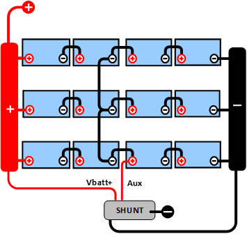
My SmartShunt has previously been monitoring midpoint deviation flawlessly, with the alarm set to 2.0% The battery bank and SmartShunt are wired exactly as per the Victron reference https://www.victronenergy.com/media/pg/SmartShunt/en/midpoint-voltage-monitoring.html and diagram below.


After taking my system offline for manual battery charging of each individual battery, I am now experiencing an issue with the midpoint monitoring. This is suggestive of a wiring issue on my part given I took everything offline, however I have taken measurements and checked everything without avail. I cannot see the error of my ways.


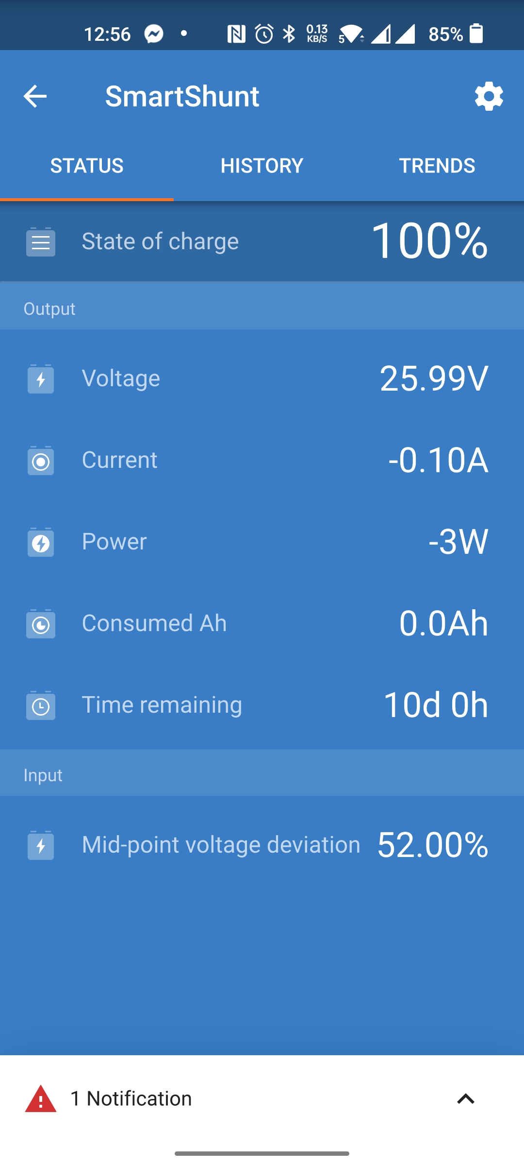
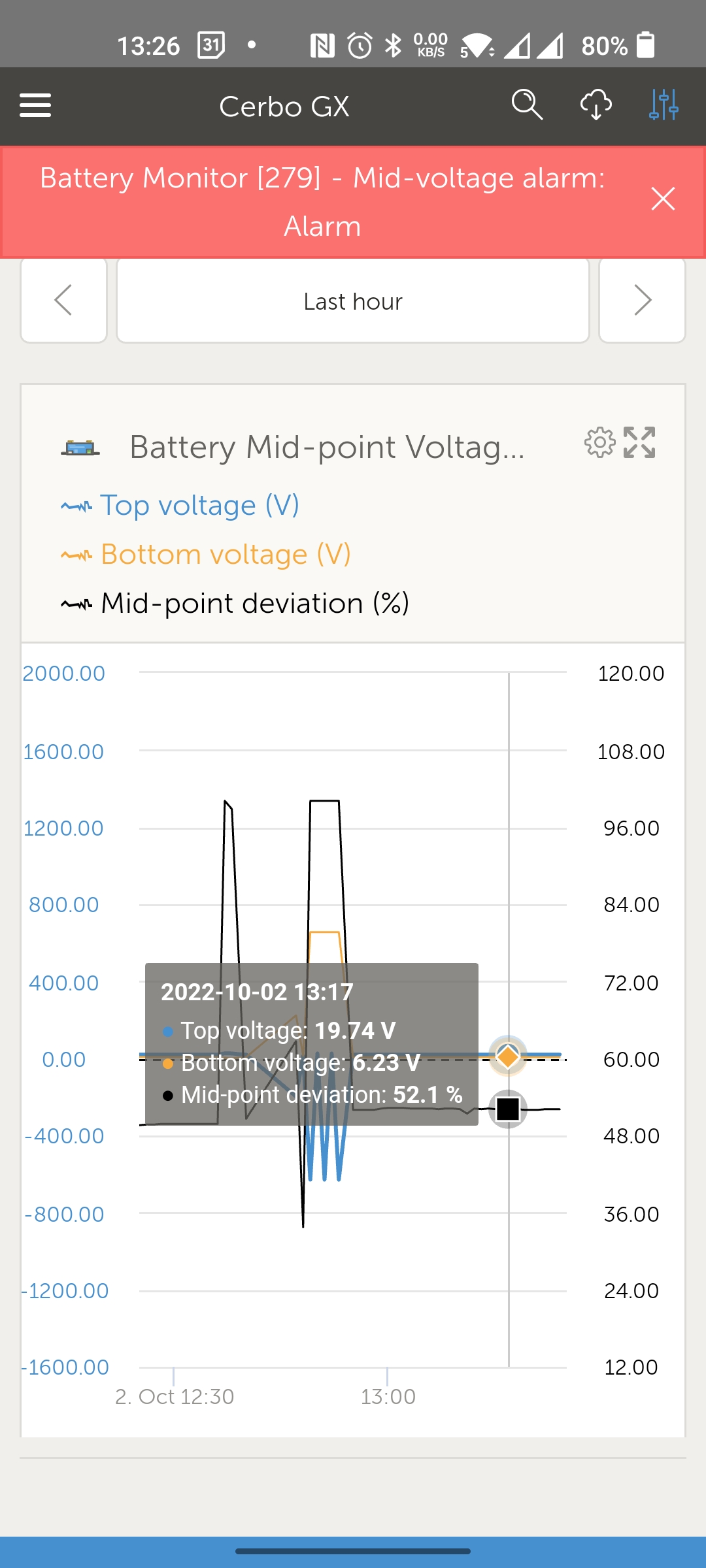
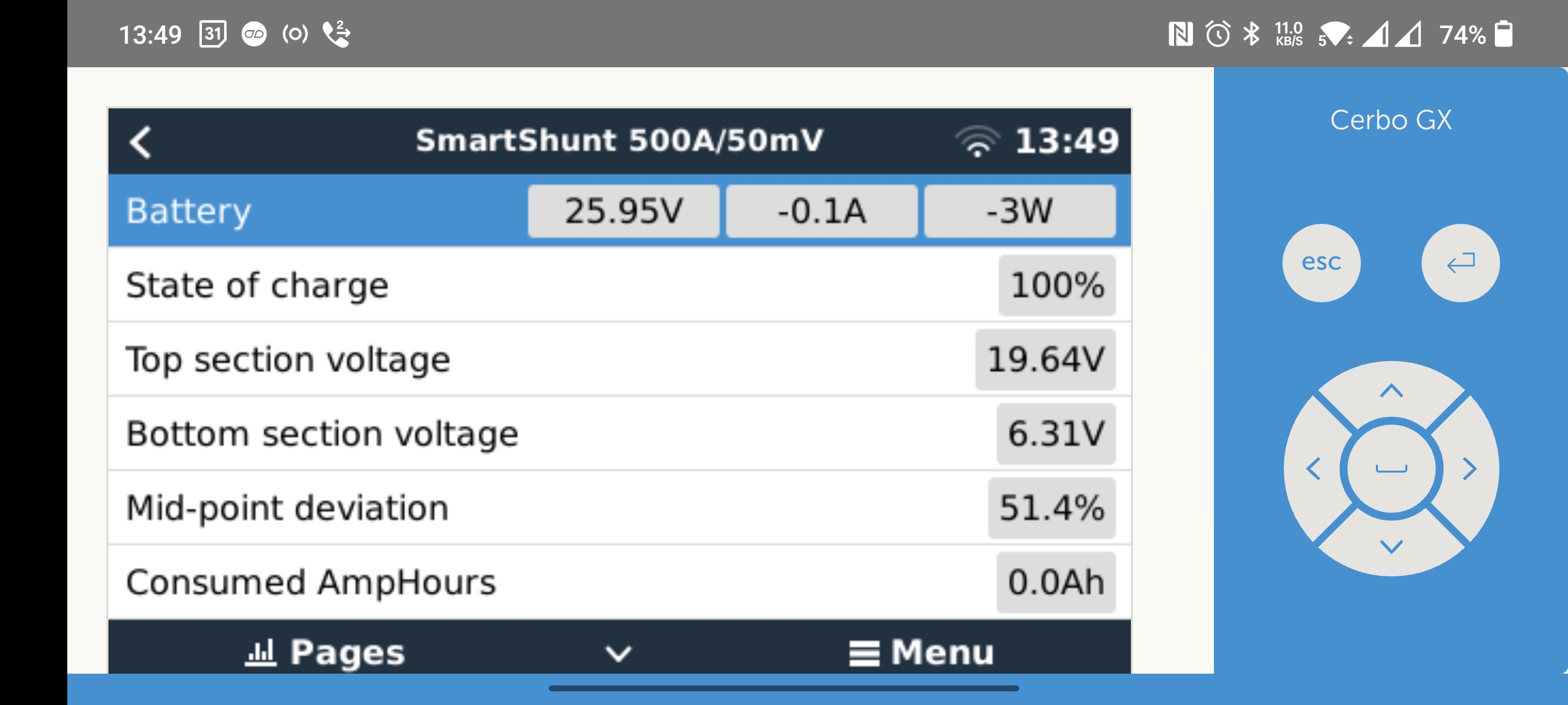
The problem is that the SmartShunt is reporting a midpoint deviation of approximately 50%. Upon further examination, this appears to be because the SmartShunt is only seeing approx 6V on Aux and not 12V for the midpoint as you would expect. If I disconnect the Aux lead and measure the potential difference between the +ve terminal of battery 3 in either string and Aux, I see approx 12V as you would expect. However, as soon as I reconnect the Aux to this same terminal and measure the pd the value drops to 6V, which obviously is what is causing the shunt to report the 50 deviation (as it's expecting to see c. 12V).

I've been tearing my hair out for an hour over this and cannot see a mistake. I attach the Victron diagram showing the exact wiring and also a screenshot from Victron Connect of the shunt.

Any help very much welcomed please!16319f2bf70465.png

screenshot-2022-10-02-12-56-15-94-30b6efbd53acd6f2.jpg


SmartShuntmonitoring
7 comments
2 |3000

Up to 8 attachments (including images) can be used with a maximum of 190.8 MiB each and 286.6 MiB total.

Tom Ranson avatar image Tom Ranson commented ·

I think I see the problem now, but I'm not sure why this is happening. Looking at the midpoint voltage deviation VRM graph I am seeing a top voltage of c. 19V and a bottom of c. 6V, hence the c. 50% deviation. The question is, why are the top and bottom voltages like this? They should, and have previously been, approximately 12V. Screenshot below (ignore the spikes which occurred during testing).

screenshot-2022-10-02-13-26-03-66-bc2aea2f1887607a.jpg

0 Likes 0 ·
Trevor Bird avatar image Trevor Bird Tom Ranson commented ·

That VRM readout looks totally wrong to me. Check out the scaling of the y coordinates. It looks very whacky indeed…

0 Likes 0 ·
Trevor Bird avatar image Trevor Bird commented ·
@Tom Ranson is it at all possible the Shunt voltage could have been accidently set to 48Volts instead of 24 volts?
0 Likes 0 ·
Tom Ranson avatar image Tom Ranson Trevor Bird commented ·
Hi @Trevor Bird , the shunt voltage is automatically detected isn't it?
0 Likes 0 ·
Trevor Bird avatar image Trevor Bird Tom Ranson commented ·
Sorry Tom, yes I just checked and you are absolutely correct. A bit mysterious isn’t it?
0 Likes 0 ·
Tom Ranson avatar image Tom Ranson Trevor Bird commented ·
Indeed. Any clue as to why my top voltage is showing as c.19V and bottom as c.6V? I can't understand where it's getting the 19V value for the top from.
0 Likes 0 ·
Tom Ranson avatar image Tom Ranson Trevor Bird commented ·
0 Likes 0 ·
2 Answers
Mike Dorsett avatar image
Mike Dorsett answered ·

When you replaced the shunt, did you use the new leads, or the old ones? I would also set up the old shunt on a "bench test" , i.e. with no current flowing through the shunt, and the 2 voltage input leads connected to a stable voltage source.

As the fault is still present, it must be related to something that did not get changed when you changed the shunt. Look for physical damage to one of the sensing leads, blown fuse, poor crimp stretched or damaged insulation.

2 comments
2 |3000

Up to 8 attachments (including images) can be used with a maximum of 190.8 MiB each and 286.6 MiB total.

Tom Ranson avatar image Tom Ranson commented ·
@Mike Dorsett as you suggested I went back to basics again. I tested the shunt on the bench with 4x 6V torch batteries in series, to eliminate the main battery bank. The problem was still present. After further continuity and voltage testing, I deduced that the Aux sensing lead was indeed faulty. There was no continuity on this lead, and albeit the fuse visually appeared ok (which I visually validated days ago) it failed the continuity test. I have now replaced the Aux lead in the production configuration and all is finally well!


What I still cannot understand is the top and bottom section readings that I've been seeing, because if due to a bad Aux lead fuse, surely I should have been seeing a top of c. 24V and a bottom (taken from Aux) of 0V? But I've been seeing 5-6V bottom. This is what has been so confusing, and led me to believe that there was no continuity issue as I was getting a reading on Aux. Your thoughts?

0 Likes 0 ·
Mike Dorsett avatar image Mike Dorsett Tom Ranson commented ·
Depending on the fuse type, a blown fuse can have a significant leakage current. Given the high impedance of the voltage measuring circuit (input to the A/D converter) This allows a measurable voltage to build up, and as the resistance of the blown fuse is somewhat variable, even depending on humidity, then the measured voltage is also variable. This can also be open to static build-up, or transferred energy from the other a/d inputs, thus leading to voltages above what would be expected, and a random voltage measurement.

even spring loaded connections to the fuse ends can carry oxidation, with loss of or variable continuity.

Glad it is all sorted.


0 Likes 0 ·
Mike Dorsett avatar image
Mike Dorsett answered ·

this looks like there could be lose or dirty connections in one or more of the battery string connections...

3 comments
2 |3000

Up to 8 attachments (including images) can be used with a maximum of 190.8 MiB each and 286.6 MiB total.

Tom Ranson avatar image Tom Ranson commented ·
Hi @Mike Dorsett , that's what I originally thought too. However I have carefully checked all connections and all voltages are as expected for every given terminal across the whole battery bank. I've also moved the aux wire from string one battery 3 +ve to string two battery 3 +ve and it's still the same result.


Referring to the above screenshot from the VRM Console, I cannot understand where the shunt is getting the 19V top section voltage from either... The battery voltage is very clearly showing as 24V (25.95).


My understanding is that the midpoint calculation takes 50% of the battery voltage as the top section value and then takes the measurement from aux as the bottom section value. So where on earth is it getting 19V top from?

0 Likes 0 ·
Mike Dorsett avatar image Mike Dorsett Tom Ranson commented ·
try putting it (the Aux input) on the positive bus bar and see if it tracks with the other input. This will show if its gone faulty.
0 Likes 0 ·
Tom Ranson avatar image Tom Ranson Mike Dorsett commented ·
@Mike Dorsett it's still giving odd readings even on the positive bus bar. But I've also now replaced the shunt and am still facing the same problem. I'm at the end of my tether with this issue as it's very basic stuff and I cannot for the life of my deduce where the issue is.


Any other suggestions please?

0 Likes 0 ·

Related Resources