Hello
i have some problems my setup
Victron MULTIPLUS-II 48/5000/70-50 GX -> grid is connected no feed in is set and ext. current sensor connected
Victron Energy SmartSolar MPPT 250/100 VE.Can, connected to inverter by ve.direct
Victron Energy Lynx Power In as a buss bar
Victron Smartshunt 500A/50mV connected to MPPT via bluethooth
8x Sharp NU-JD540
JK-BMS B2A24S20P {not connected to inv via CAN} on the 16 x 304ah 3.2v prismatic lifepo4 new battery cells
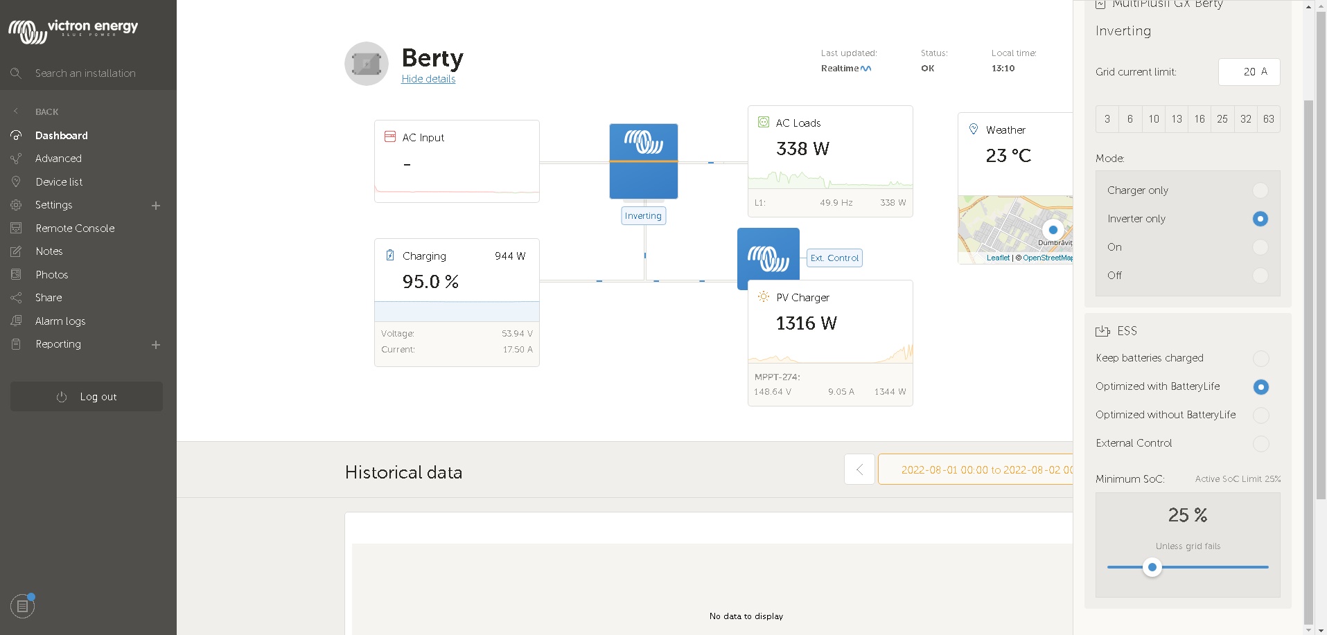
1. When inverter is set to "inverter only" the displayed load is 300W and more -> Grid inv inv only.jpg
but when inverter is set to "ON" the displayed load is 150W ->200W -> Grid inv ON.jpg
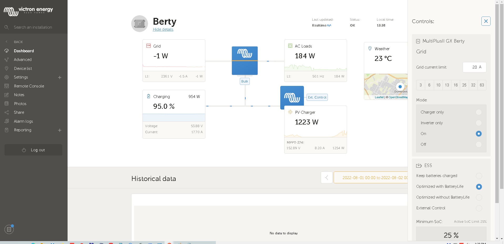
All this with the same load no load added or removed, write this to not get answer like you added or removed load!!!
Q -> what is the reason for different load displayed when inv is set to Inverter only or ON?
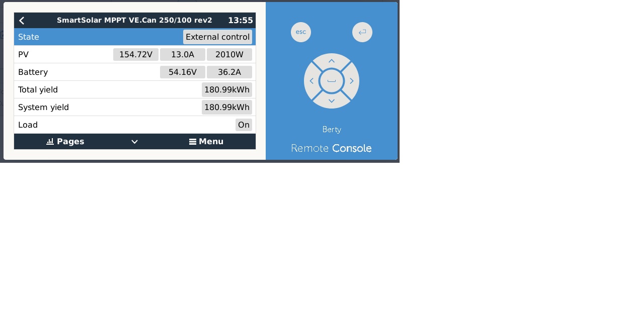
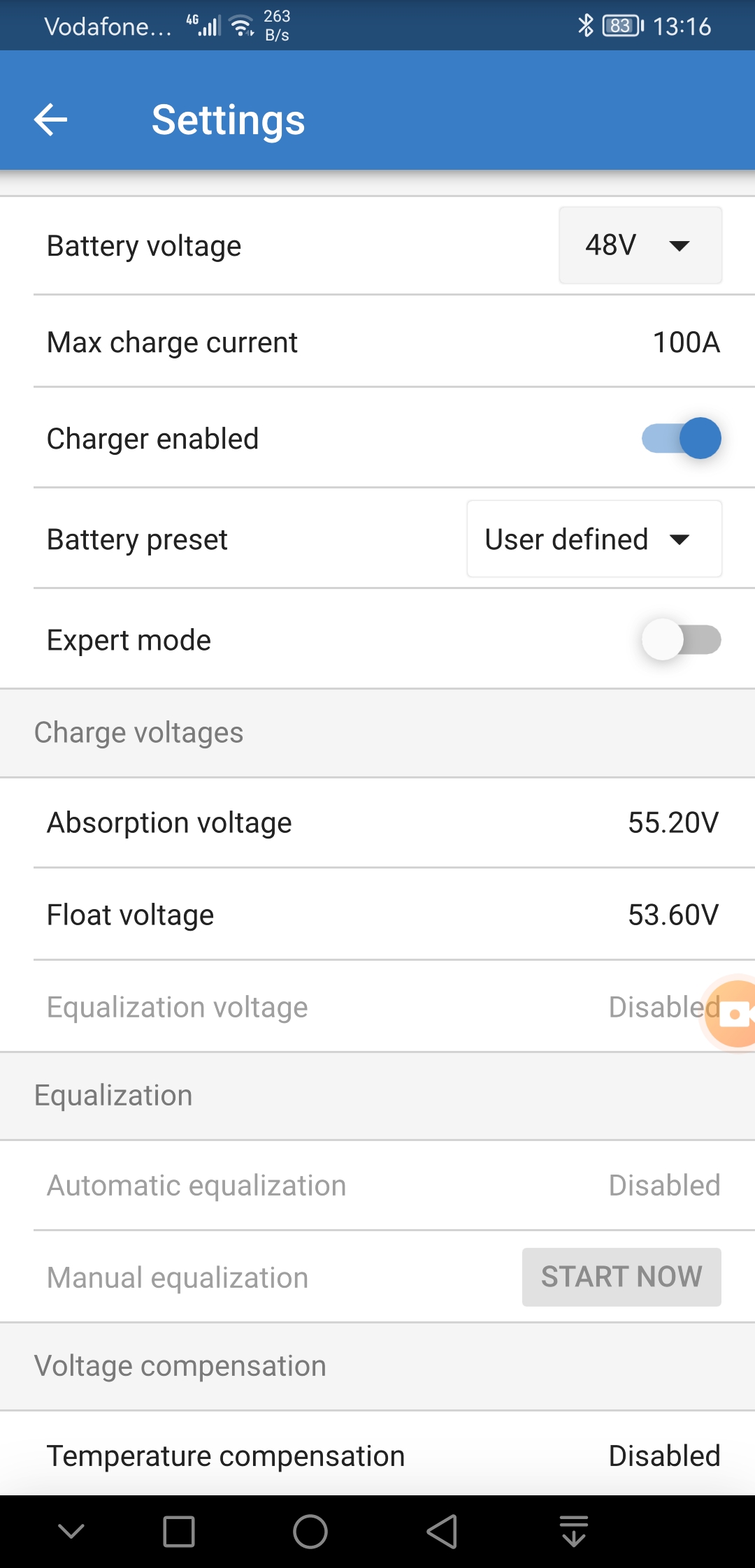
2. Regarding MMPT settings, ext control is displayed in VM, and different V in Victron connect and remote VM
in remote console MMPT -> Networked Operation charge voltage is set 60.8 but in the MMP via Bluetooth voltage is set to 55V
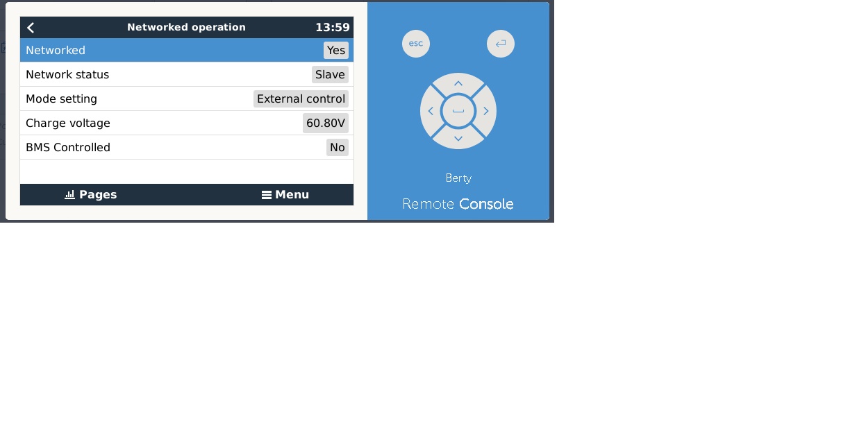
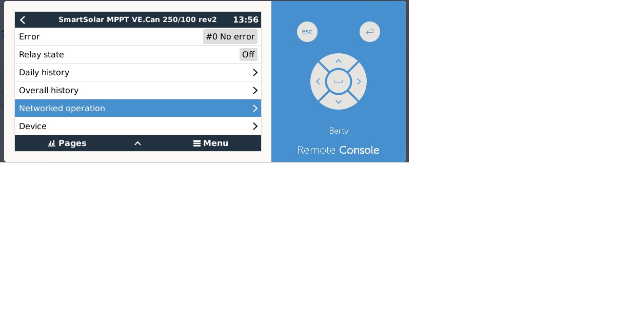
Q -> what is the reason for different V
Q -> is there a way to fully control MMP from VM remote console like from Bluetooth APP ?
Q -> what is the reason "ext control" is displayed? what device is controlling the MMPT?
Q -> in MMPT absorption is set to 55.2 and batt voltage is still rising, why?
3. In the VM no matter what state of charge battery have, displayed value do not go under 90% even when inv was disconnected due to low battery
4 unfortunately JK BMS do not working as it should and do not turn off charging when one cell reach the set "over voltage value" which is 3.55
ess config is attached
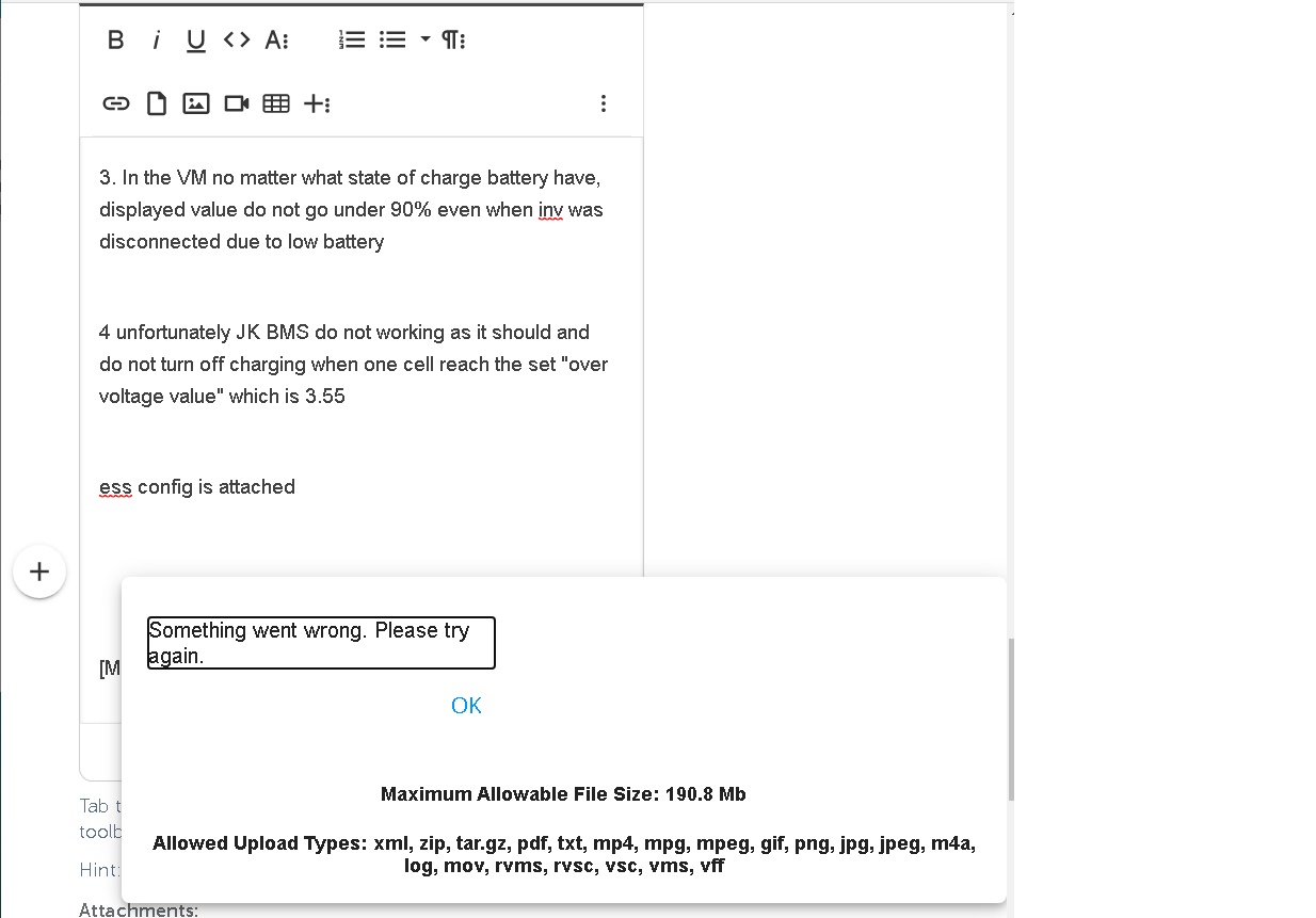
when i try to upload RVSC file
i try to make it zip rar let it in RVSC format -> have the same error
https://www.youtube.com/watch?v=7NOL2cFnO1g&feature=emb_imp_woyt