question

rikhf avatar image
rikhf asked

LED's on Lynx Distributor. Weird behavior.

Hi all, This question is asked in another topic as well but I didn't get any answer so I make a new question here.


I have 2 distributors on 1 side of the Lynx Shunt. 1 is connected straight to the shunt and one is one and a half meter further. I connected the Distributor which is connected to the shunt with the RJ11 cable that came in the box and all is well. Then I extended the cable that came with the other Distributor but all fuse led's turn red and the middle one yellow. The manual doesn't say what this means. I have tested the cable. All threads are well and there are no shorts. Why do I get this behavior?


20220811-185828.jpg

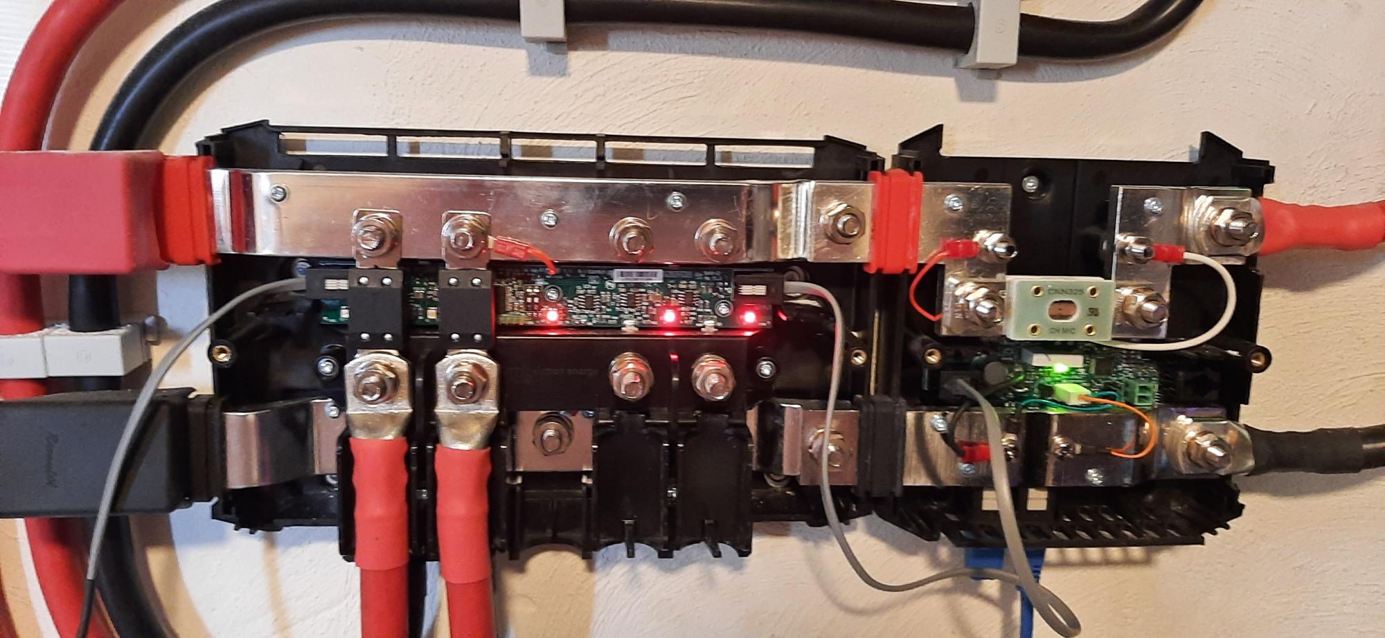
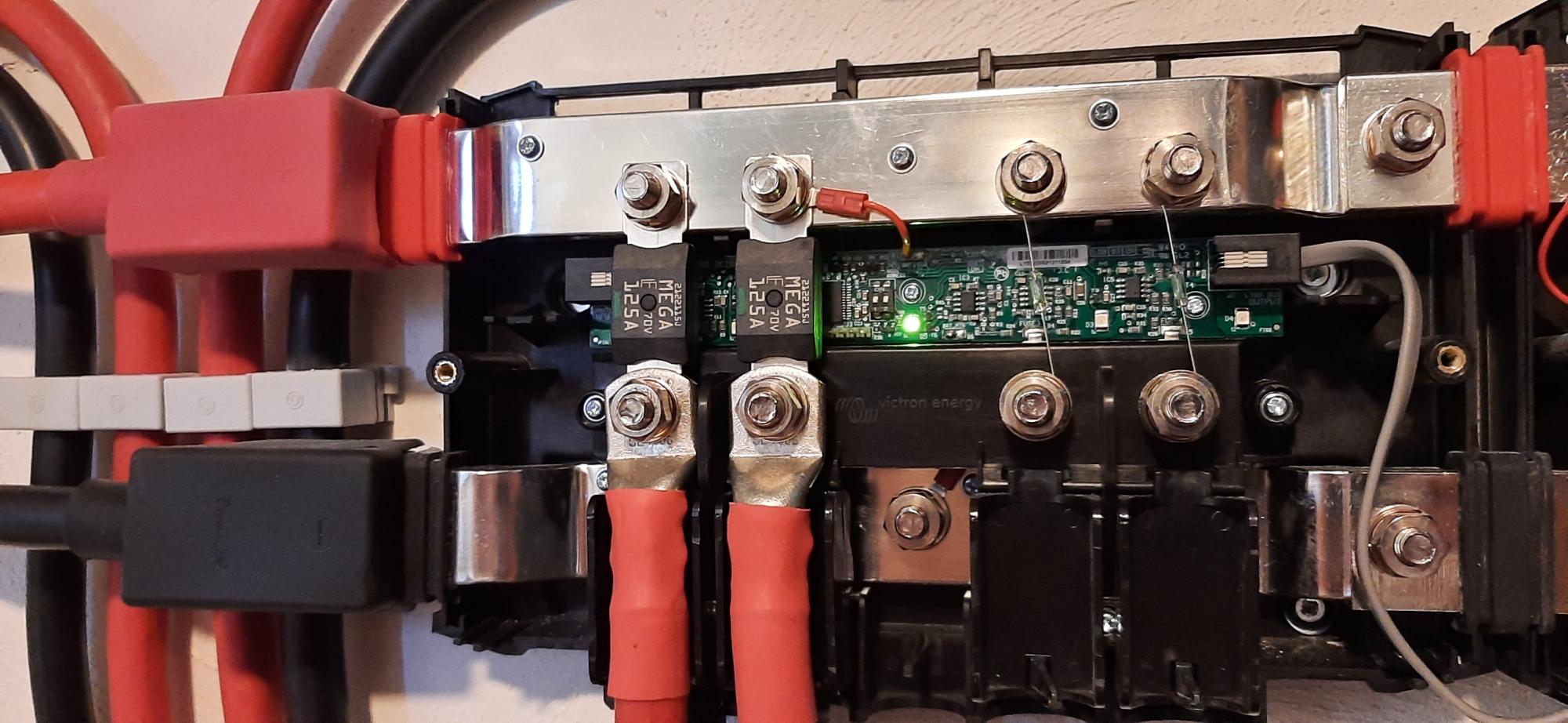
On the left is the extended cable to the second Distributor.


20220811-185837.jpg

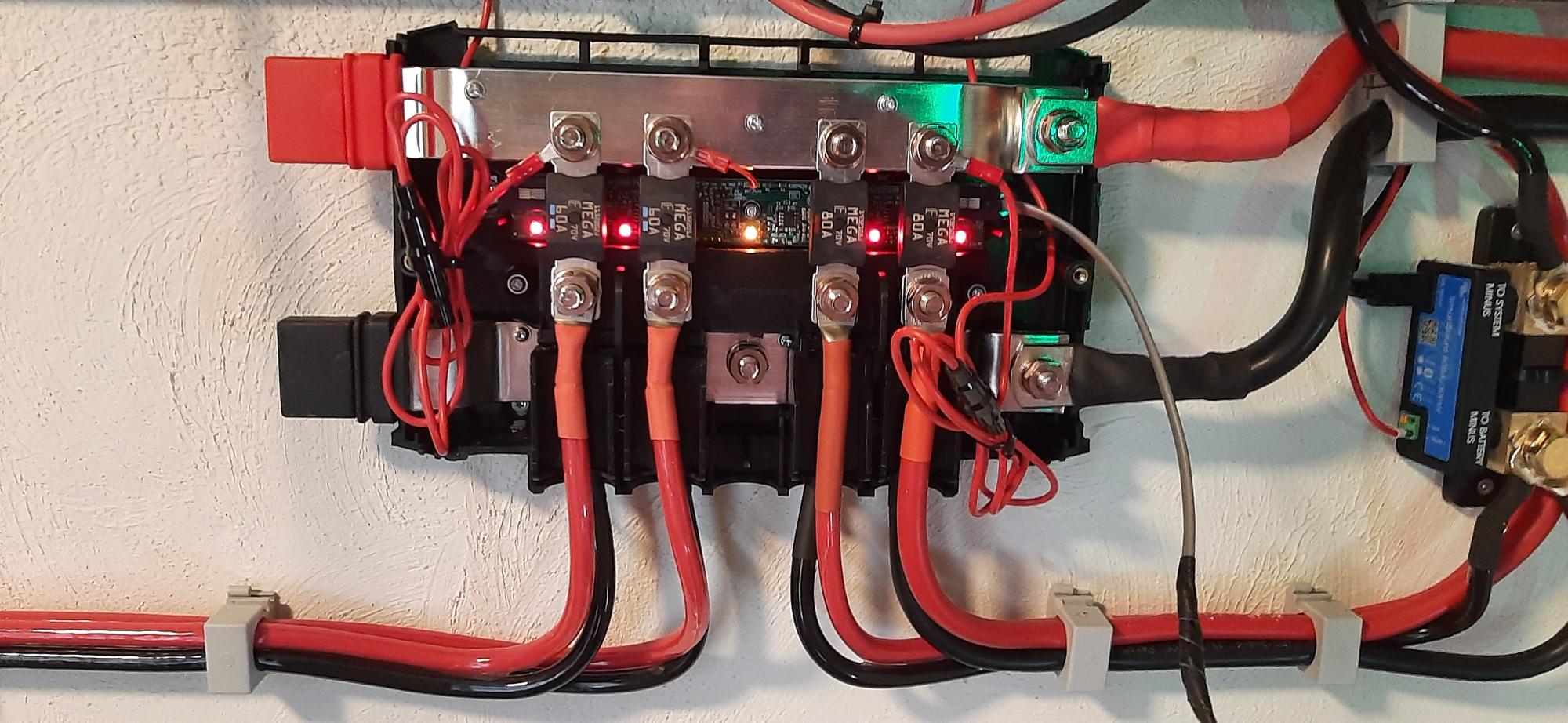
And here is the one with the weird behavior.


Can anyone explain this or have some advice what I should try?

Thanks in advance!

Rik

lynx distributorled
2 |3000

Up to 8 attachments (including images) can be used with a maximum of 190.8 MiB each and 286.6 MiB total.

5 Answers
bathnm avatar image
bathnm answered ·

Have you adjusted the dip switches on the second unit? There is a pair of very small dip switches which sets the units address. If they are both at the same setting you may have an issue. Just adjust one dip switch to the on position on the second unit.

2 |3000

Up to 8 attachments (including images) can be used with a maximum of 190.8 MiB each and 286.6 MiB total.

rikhf avatar image
rikhf answered ·

Ok. No I didn't do that. Didn't realise they have dipswitches on board. Thanks @Bathnm .

2 |3000

Up to 8 attachments (including images) can be used with a maximum of 190.8 MiB each and 286.6 MiB total.

rikhf avatar image
rikhf answered ·

Unfortunately that didnt work. Reading more into these dip switches learned me that they are to determine if the distributors are #A, B, C or D. But only on the Lynx BMS, not on the shunt. On the Lynx shunt one cannot see the state of the fuses in Venus OS! How stupid is that!?

So I cut the data wires in the cable but the result is still the same. Then suddenly I had a hunch and connected the home made cable to the distributor that is working well on the original cable. All fuses red and the middle light yellow. So this cable isn't well though I measured again for continuity and shorts. Isn't that strange? I will look up a usb cable and let that be powered by the Cerbo's USB that is supposed to power the touch screen (which I don't use) and see how that goes. I will post the results.

2 |3000

Up to 8 attachments (including images) can be used with a maximum of 190.8 MiB each and 286.6 MiB total.

rikhf avatar image
rikhf answered ·

Ok, I made this cable:

snoertje-voeding-usb-distributor.jpg

Put it in the distributor and everything is working now. So if someone wants to make a cable as well, here is your example.

Guess I'll never know why it didn't work out with the other cable. Still very dissapointing that it is not connected in a way I can see the fuses status on the Cerbo...


2 |3000

Up to 8 attachments (including images) can be used with a maximum of 190.8 MiB each and 286.6 MiB total.

rikhf avatar image
rikhf answered ·

In the mean time I changed 2 fuses for 70V rated ones and connected the 2 not used spaces by means of a little 5A fuse. Red lights are gone now. No need for fuses off course because there is no current flowing so a little wire will do as well.

20220814-115510.jpg


20220814-115510.jpg (210.4 KiB)
2 |3000

Up to 8 attachments (including images) can be used with a maximum of 190.8 MiB each and 286.6 MiB total.

Related Resources