question

Alistair Warburton avatar image
Alistair Warburton asked

Is Passthru entirely disabling the inverter, or just the charger (Charge control)

Hi Folks,

I just finished putting together a little interface, that's almost too grand a title, to manage the charge current limit via Modbus.

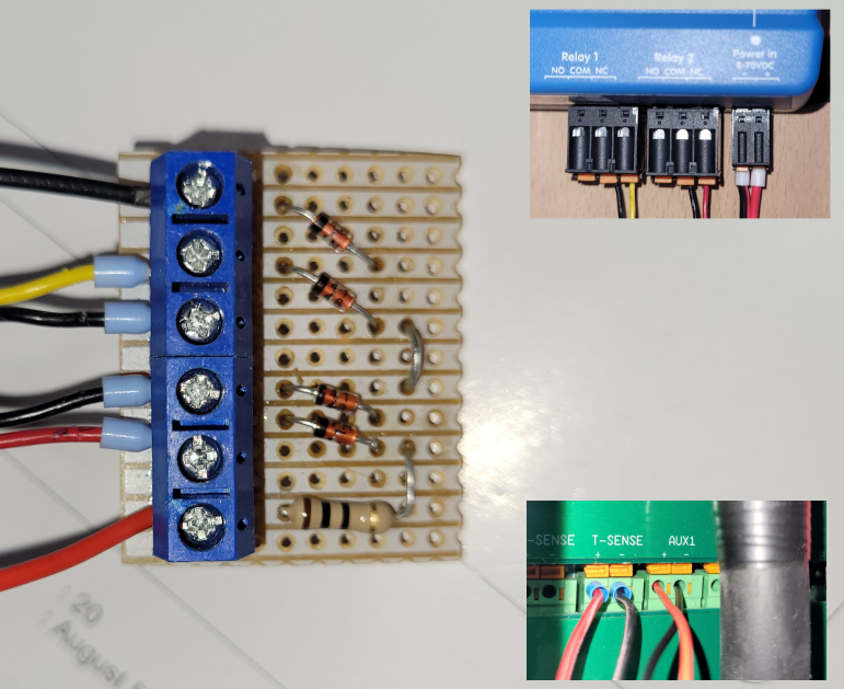
Its a simple board with 4 diodes and a current limit resistor, although the latter is not strictly necessary. The diodes are in a string with the forward voltage drop's providing a reference voltage on the Aux in terminal.

My Cerbo GX is then used to short out some diodes giving selectable charge currents, implemented by the charge control assistant.

charge-control-modbus.png

Using the above I get 4 circa 750W steps, in my case starting at 0.

It works very well and I can now set a charge limit, including no charge, using Modbus from NodeRed to control the relays.

cl-flow.png

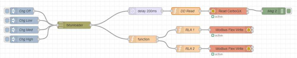
The flow is only for testing right now, hence the inject nodes, but it opens a load of possibilities.

In case anyone is wondering, I have set the multi to shut down the charger when 0 current is requested. This results in a Passthru, state as opposed to Bulk with 0 current, and I was a little concerned that doing this would prevent the Assisting, state from being achieved but I just put a pizza in; that's my kind of testing; and set an AC current limit of 4A.

The multi went into assisting with no issue which is just as well because the alternative was an overload trip and me looking for a TORCH!

I have to say that I am a little confused as to why a module/interface like this doesn't exist, given its simplicity and usefulness, but then I guess you could argue that charge current limiting should be available as a writable parameter in the first place.

I know this isn't a question as such, given that my pizza answered the question I originally asked, but I am posting anyway because charge current limiting/self consumption and many other related queries seem to come up all the time, and have been doing so for years.

For anyone interested in the detail...

cc-board.png

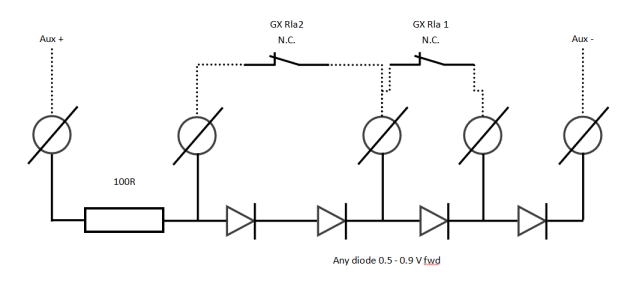
The Aux port has a pullup, circa 600 Ohms I think, on the +, holding it at 5V if there is no current draw. The diodes/relays act as a selectable voltage reference, pulling Aux+ down to a little over the sum of Vf on all diodes that are not bypassed by a relay contact

The switching is binary, 0-3 with bit 0 on Rla1.

I know this is very simple, that is the point; I also know that there are many other ways to go, I could have used a PWM pin on the PI for example. However doing it this way means the relays can be operated via Modbus / MQTT / GX UI / VRM portal, which think is worth the minimal effort.

Additional relays could be used to force on, or off, the charger so the relay assistant could probably be made to do all sorts of stuff by modifying the output of this circuit.

Of course you can do just about anything with Node Red so I probably will not mess with the programmable relay stuff but it is worth pointing out I think.

Thoughts? could I have picked a better way? happy to learn.

MultiPlus Quattro Inverter ChargerModbus TCPcharge current limit
cl-flow.png (45.6 KiB)
cc-board.png (25.8 KiB)
2 |3000

Up to 8 attachments (including images) can be used with a maximum of 190.8 MiB each and 286.6 MiB total.

5 Answers
shaneyake avatar image
shaneyake answered ·

This can all be done via NodeRed directly or Modbus.
You just need to install the ESS assistant and set the ESS mode to external. This will give you fully control of the inverter. Charger rate in watts, discharge rate, connect to grid, disconnect from grid, export, import, etc. It takes a little of understand to get all this functionality as it is based on input power but not hard to do in NodeRed.

I would highly recommended doing this in software rather, so that you can use the relays for other things like controlling loads or AC-2 output which doesn't have software control.

2 |3000

Up to 8 attachments (including images) can be used with a maximum of 190.8 MiB each and 286.6 MiB total.

Alistair Warburton avatar image
Alistair Warburton answered ·

That was exactly the sort of comment I was looking for, would you happen to know if there is any documentation?

Obviously I will search for it ASAP. Despite reading a load of posts on ESS over the last few months, and asking questios, this is the first I have heard of 'External' mode.

Thanks I apriciate the input.

8 comments
2 |3000

Up to 8 attachments (including images) can be used with a maximum of 190.8 MiB each and 286.6 MiB total.

bathnm avatar image bathnm commented ·
For those on a boat or RV, the use of ESS is not possible. We can not have the output of the Shore side of the inverter live as if someone pulls the shore cable they have a live cable in their hand.
0 Likes 0 ·
shaneyake avatar image shaneyake bathnm commented ·

When in ESS mode3 the inverter doesn't have to be actively inverting.
Also ESS running or Power assistant active run the same risk of a live input as input an output of the inverter are coupled when input contactors are closed.

But the inverter is continuously checking for grid presence and if gird is lost the inverter shuts down till input contactors are open 2-20ms. This is the case for Power Assistant or ESS.

0 Likes 0 ·
bathnm avatar image bathnm shaneyake commented ·

The victron manual is very clear. So in these situations people need to find alternative solutions.

When not to use ESS

  • Off-grid systems - either with or without generator.

  • Marine systems.

  • Automotive systems.

  • Inverter priority, also known as 'Intentional islanding“ or 'Ignore AC' input systems.


0 Likes 0 ·
Alistair Warburton avatar image Alistair Warburton bathnm commented ·
No argument from me... I was searching for, asking about how to do this without ESS and everything I found, from the point of view of comments on previous questions as well as answers directly to me was pointing me to ESS.


There is such a comment on this thread...

My problem is, well was, that I didn't understand/appreciate either the implementation or limitations for ESS based control and assumed that someone recommending it as 'the' solution did, or at least new something I didn't.
[ Not setting the bar high there :-) ]

I will be using my less than elegant solution unless someone gives me cause to rethink. I may even insulate it and put in a box!!

I very much appreciate the clarification though, thanks.

0 Likes 0 ·
shaneyake avatar image shaneyake bathnm commented ·

The manual here is referring to ESS under normal victron control scheme, not external control which is what I have suggested.


The ESS assistant basically just gives you full inverter control over VE.Bus instead of limited control inside the inverter. Maybe oneday they will rename it to External Control Assistant and ESS will only refer to the ESS control loop on the GX. I am not suggesting using the ESS control loop in the situations listed above.

So as an alternative solution you can use this external software control to run your own control scheme for these situations.

0 Likes 0 ·
bathnm avatar image bathnm shaneyake commented ·
Interesting view, I had never seen it portrayed that way.
0 Likes 0 ·
shaneyake avatar image shaneyake commented ·

VIctron calls it Mode3
Here is a good place to start. I am happy to answer any specific questions.
https://www.victronenergy.com/live/ess:ess_mode_2_and_3

0 Likes 0 ·
Alistair Warburton avatar image Alistair Warburton shaneyake commented ·
Thanks, see below...
0 Likes 0 ·
bathnm avatar image
bathnm answered ·

Neat. You could install the NodeRED victron plugin and then you can control the relays directly as opposed to through Modbus.

I didn't want to control charge current, but did want to prioritise my solar over the shore input. So I use assistance and the aux ports to disable and enable Ignore AC. I also have the generator start/stop assistant installed so if solar cant keep the batteries in good shape the generator starts and causes the aux port to open, which disables Ignore AC. Then when the batteries are full again the generator start stop assistant causes the aux port to close and ignore ac is once more disabled. This way I do not have to do anything.

Assistance are really good and there is a lot you can do without needing other control systems.

2 |3000

Up to 8 attachments (including images) can be used with a maximum of 190.8 MiB each and 286.6 MiB total.

sharpener avatar image
sharpener answered ·

A closely related question. I have a Multi II-GX 5k (and already use NodeRed to vary inverter power and charging current limit according to SoC and time of day). I would like to use the Aux1 input as a Home/Away switch to change the behaviour of my NodeRed flows accordingly, but I can't find which node (if any) allows me to interrogate this input, is this possible?

8 comments
2 |3000

Up to 8 attachments (including images) can be used with a maximum of 190.8 MiB each and 286.6 MiB total.

Alistair Warburton avatar image Alistair Warburton commented ·

You peaked my curiosity...

I think, not tested yet, that temperature inputs from GX devices are available as Modbus & VRM data (I may be wrong and will check shortly)

Either way the temperature inputs require an LM335z, which ST will mark as an LM335A, where z/A are differentiating supply packaging not electrical spec.

The sensors are temperature dependent Zenner diodes, with a cal input that you can ignore, and have a 10mV / C offset from 0.98V@25C.

I think the Cerbo GX is a 3.3V rail so that would limit resolution to about 50C, 3.1V ish.
If the input is pulled to 5V then you could probably max the sensor out at 100C, it rather depends on the specifics of the internal circuit, which may well be clamped.

V/C 0.01


C V
-20 2.53
-15 2.58
-10 2.63
-5 2.68
0 2.73
5 2.78
10 2.83
15 2.88
20 2.93
25 2.98 Cal
30 3.03
35 3.08
40 3.13
45 3.18
50 3.23
55 3.28
60 3.33
65 3.38
70 3.43
75 3.48
80 3.53
85 3.58
90 3.63
95 3.68
100 3.73


To be ABSOLUTLY CLEAR here...

This is data I got from the spec sheet after looking at expert answers to questions about temp sensors. I am not 'stating fact', just what I intend to test.

The forward voltage of an LM335 is circa 0.7V and this will produce a Reverse Polarity warning for the temp sensor input/device if it is detected.

Based on several other question's/posts it looks as though enabling a sensor, or digital input, will create a device and assign it an instance/ID which should then show up in VRM and be available over Modbus. Apparently multiple sensors/inputs of the same type get different ID's and share a value register/s.

Enabling them on the GX defiantly works, haven't tried Modbus to access them yet.

I am seeing the temperature input and digital input, I set it as a bilge pump, in the VRM device list, but not the tank.
The tank has shown up in the advanced list of widgets where, oddly, the temp is missing.
(Possibly because it is reporting disconnected right now.)

The tank has shown up on the remote console over my LAN.

If temp works as expected than it is very likely that tank sensors will too.
Tank inputs apparently accept 0-240 ohms and read 0-100%.

I haven't checked yet but they are probably just pulled up with a resistor, although they could have a constant current drive output, reading back the voltage in either case, or possibly even a current sense resistor, internally on the - side, the latter being the least likely IMHO, but I will check. I am all but certain the two input types are different, to accommodate sensor characteristics, but I haven't worked out the spec yet

There is probably a document somewhere out there that explains all this but I haven't found it.

I will update this comment later, when I have tested the Modbus end of stuff

0 Likes 0 ·
Alistair Warburton avatar image Alistair Warburton Alistair Warburton commented ·
Yes DI's work from Modbus, the tank and temp also have valid ID's so I expect they will too, and once I have the electrical spec pinned down, I see no reason that they couldn't be used for general analogue Inputs where Node Red is concerned.

Grated you will have to put up with the default named in the UI's


That was a very long winded way of finding out that DI and both AI types can be used in Node Red via Modbus and that Tanks and Temps 'should' be able to be used as general AI, with some range limitations and a bit of care.

0 Likes 0 ·
shaneyake avatar image shaneyake commented ·

Unfortunately the Multiplus-ii GX doesn't have any of the GX i/o exposed. Probably easiest to use something like an Ardunio to send MQTT messages to NodeRed connected to your switch.

The temp input is actually readable but telling the inverter the battery temp is something different can have unintended consciences.

0 Likes 0 ·
Alistair Warburton avatar image Alistair Warburton shaneyake commented ·

You sure?

from the manual...

4.1.10. Programmable relay

4.1.12. Programmable analog/digital input/output ports

Assuming the relay can be set to manual it could be used as a switch right on the web UI or VRM UI.

I cant test that because I dont have one but it seems like a reasonable conclusion given the available 'published' info.

I could well be wrong though, if there is one thing I am learning quickly its that there seems to be many reasons why the logical thing isn't a thing at all!

BTW, is Node Red on the internal GX here or an external device as I assumed?
If external then it can have whatever physical IO you want to add to it, not that you would see it in VRM or on the device.

0 Likes 0 ·
shaneyake avatar image shaneyake Alistair Warburton commented ·

@sharpener asked about the Multiplus-II GX which has a GX built in.

Because the GX is internal to the multiplus the only IO that is exposed is the Multiplus's.
You can see a photo here:

https://www.victronenergy.com/inverters-chargers/multiplus-ii-gx#high-quality-photos

If you don't want to do an external device then the temp sensor is the only way to get an input into the GX via the multi.

Unfortunately other multi inputs are not available via Dbus, it would be nice if we had K1, Aux, AC-2 control or could read all the inputs but we can't and will never be support as far as I am told.

0 Likes 0 ·
sharpener avatar image sharpener shaneyake commented ·
In my setup the Pylontech BMS supplies the temp information, so perhaps as it knows it is a Lithium system the GX will not do anything with the data from the external sensor (which came with the Multi but is still safely in its packet).


Will it be safe (ish) to connect this and see if I can read its value even if it has nothing to do with the battery? Which Aux terminals does it need to go to?


If that works and does not cause any upset then maybe I can connect a switch instead and interpret the resulting "temperature readings" to determine the switch position.

While I am writing, could you also please tell me if there is a quick way to save the Node Red visual flow diagram e.g. as a pdf or png or jpg?

Many thanks.


0 Likes 0 ·
sharpener avatar image sharpener sharpener commented ·
PS I now see the temp sensor has its own terminals.
0 Likes 0 ·
shaneyake avatar image shaneyake sharpener commented ·

Yeah, a CAN bus battery should overwrite the temp data that the system uses. Just turn off shared temp in DVCC if it isn't already off. I was just saying there could be unintended consciences like if CAN is lost, I am not sure what happens.

As far as I know you can't export jpg. I normally just take a screenshot.

0 Likes 0 ·
Alistair Warburton avatar image
Alistair Warburton answered ·

I couldnt get the contrib_victron... nodes to work, because the config node showed up blank so I cant comment on those. For Modbus/MQTT and probably the victron nodes anything you can read the state/value of could be your trigger.
If you want to have perameters, or a physical switch on an input, trigger or modify a Node Red flow just pick something accessible that you arenot using for anything else.

Just a first thought... A GX device relay. Why because you can set it, assuming it is in manual, from all UI's and if you assign it a function you can set it based on any number of things using the relay assistant.

I dont think inputs are exposed directly as modnus registers, the shhet will tell you, and I cant comment on the victron nodes with any authority, sorry.

BTW, the node red instance I am using is running under Home Assistant so that is likely the cause of the Victon stuff failing to work in my case.

Untill recently my GX was a CCGX so not many options as I understand it.
With my second inverter I have installed a Cerbo GX so putting alternate FW on that, large with Node Red, is that right? is probably a good plan.
If , when, I do that my HA automations can talk to Victron notifications on different Nodered instances without much of an issue and I will probably run Influx/Grafana on the HA box as my multi channel energy monitor and all IOT kit is there.

I just looked at the ESS manual 'again' and so far as I can tell HERE 'External mode (3) will only do some of what I want/need and then only with an external control loop... (which in my opinion is asking for troubel)

I had discounted ESS as an option for these reasons without going any deeper.

Note... From the page above...

"The point of control is the AC..." "...maximum battery discharge current is ignored..."


This is what pushed me down the charge control route in the first place.

I MUST have the unit in passthrough, when the charger is disabled, whilst retaining power assist on top of an AC limit that respects the device feeding the inverter.

(Bulk/float but with 0 charge current would have been ok but as 'Passthru' supports 'Assisting' it is the better/cleaner choice)

I don't want to limit AC current to limit charge, that hurts my Assisting capability and my wife cant get her head around limiting loads.

I don't want to bypass/replace/or even mess with charging/discharging parameters other than limiting average charge rate to manage import, actually cross charging in my case but that is another unsupported story.

I want the flexibility to manually control everything from the standard UI's whilst retaining the ability to flip those manual switches/setpoints with Node Red or similar.

4 diodes, 1 resistor and 2 built in relays and the Charge current assistant, get me all that.

Sorry but I am still not seeing the downside. If I set a hard DOD/voltage limit, as I have because it would be stupid not to nothing above compromises that and there is no external control of charge limits or charger profile, other than throttling/disabling it.

Am I missing something? am I interpreting the ESS manual incorrectly perhaps?


2 |3000

Up to 8 attachments (including images) can be used with a maximum of 190.8 MiB each and 286.6 MiB total.