Newbie to the forum...
I’m hoping someone can help me.
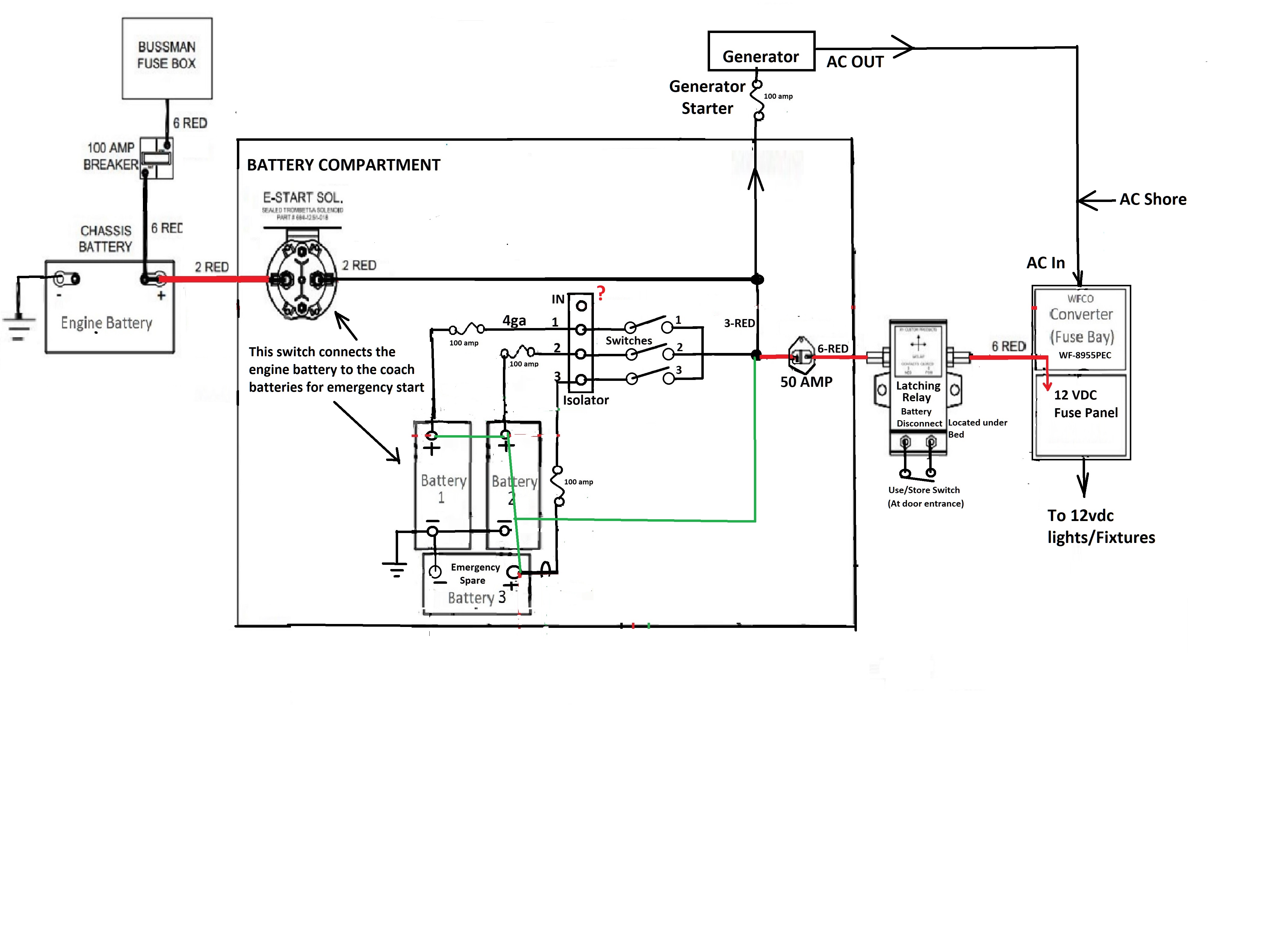
I purchased the Victron FET Isolator thinking this would be a simple task; connect the charging circuitry to the “IN” and batteries to the outputs 1, 2, 3...simple...right?? Well, I can't figure it out.
Here is the problem...Referring to the wiring diagram below...The batteries are charged by either the converter or the alternator in the engine compartment. The same wires that provide the charge to the batteries also supply 12Vdc to the 12Vdc fuse bay that powers all the 12v circuits in the coach.
The green lines in the circuit represent the original wiring configuration...as one can see, the batteries are in parallel, and all connect to one point.
My goal was to avoid putting all the batteries in parallel by using the isolator and install 3 fuses and 3 switches so I could switch in/out any battery combination I wanted...including having a emergency spare.
To complicate things...the “E-Start Sol” is a momentary switch connects the engine battery to the coach batteries; this is in case the engine battery goes dead, you can start the engine from the coach batterie(s).
I can't figure out how I can connect up the "IN" on the isolator and still maintain the functionality. I'm not sure it's possible to incorporate the isolator and I might have to just connect the output of the switches to the common point like the original circuit.
I was thinking that perhaps I could find the 12Vdc outlet of the Converter and run that to the "IN" of the isolator, but then the issue is the E-Start Solenoid connection which is to connect all the batteries together...can't seem to figure that out using the isolator.
Anyone?