Hello, I bought easysolar 2 gx 48/3000. connected 1,8 kWp of panels to its mppt, lifepo4 battery 48v 230 Ah with BMS can bus, Meter et112. The problem occurs when the battery reaches 100% and the BMS disables charging ... at this point there are continuous restarts until communication with the on-board mppt charger is lost. only way to reset and manual restart. Another detail that I would like to fix is that I have a fronius inverter connected upstream with input to the grid ... the loads are powered by the fronius by depowering mppt on board instead I would like to power the loads with mppt victron and enter all the fronius. do you have any advice? thank you very much
asked
Problem easysolar 2 gx
In properly configured system BMS should never intervene i system rutine operation.
BMS intervenes only when there is something wrong with the battery.
To answer the other question we need a diagram of your system with complete technical information on all components.
thanks for your help. The BMS is connected via can bus and sends to the victron the state of charge at 100% to stop charging, it does not cut the power to the battery. how could you do otherwise?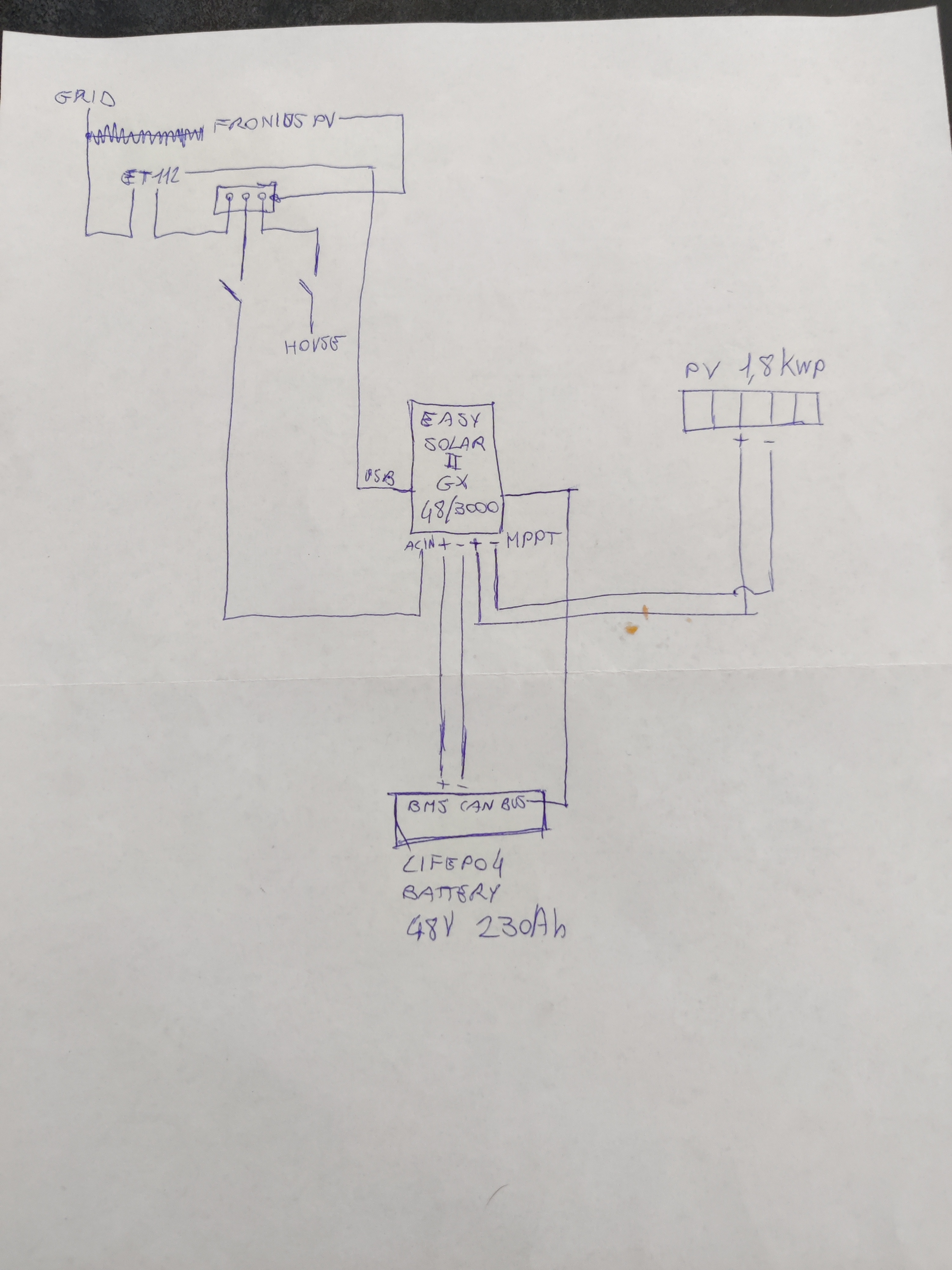
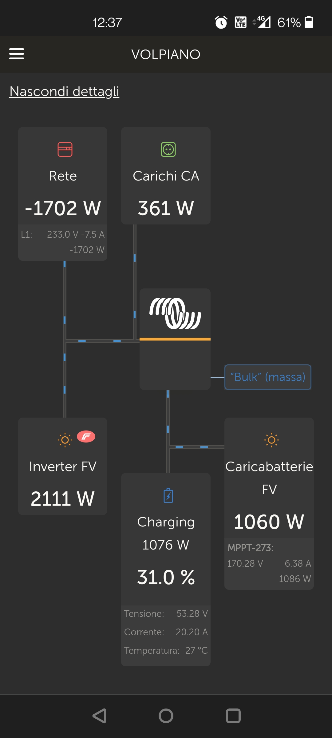
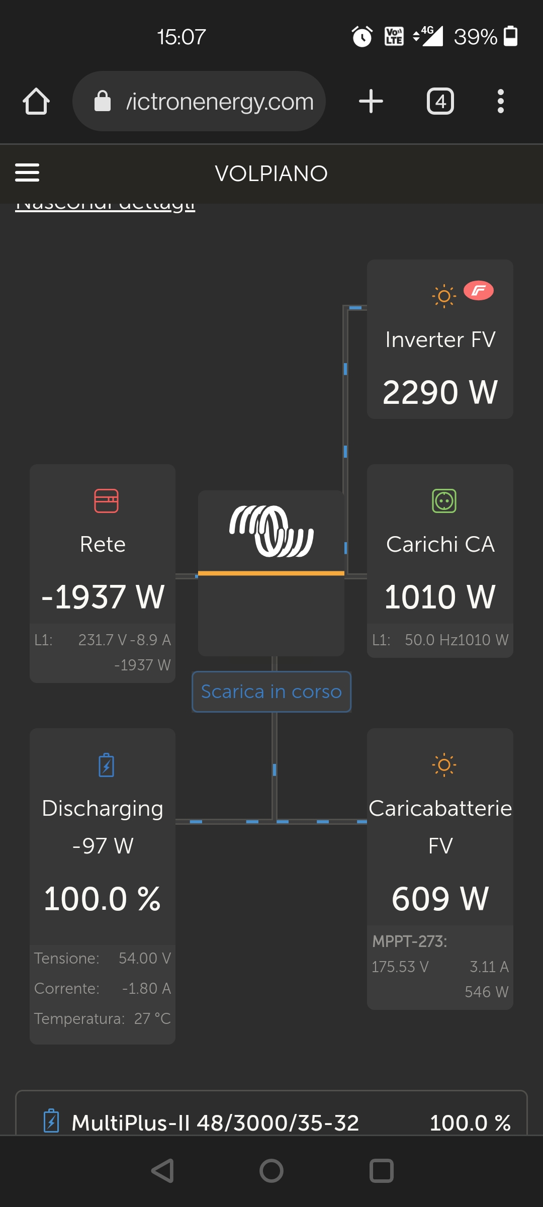
Screenshot_20220522-123730.jpg
at this moment i am charging the battery with 20A as set in the DVCC, the ftv connected on the victron could produce about 1500watt at this moment but it is reduced to 1000 due to the DVCC. the 361 watts of load are taken by the fronius but could be taken by the victron mppt by feeding all the 2111 watts produced by the fronius into the grid
Do I understand it right that you do not have any load connected to AC-out of your EasySolar?
What is the purpose of this system?
Do you have ESS assistant loaded?
The standard setup should have your house load connected to AC-out of the EasySolar.
Fronius can stay on the AC-in side if it is bigger than 3kW.
System should measure the SOC independently from BMS by means of SmartShunt or EasySolar's internal measurements.
BMS should never be used as part of the normally working system.
BMS tells the system to stop using battery when there is something wrong inside the battery. (high or low cell voltage or high or low temperature or overload)
-yes, on the AC out I have not connected anything for now, I will do it for critical loads but only after the system is stable and does not restart without reason interrupting the outputs.
- the system is self-consumption with storage. I store solar energy for use at night and for peak loads.
- ess system loaded and working.
The manual also shows the connection diagram as mine called grid parallel and in fact everything works very well apart from these problems.
The fronius is 3 kW.
For the BMS, what I have mounted is the seplos, very similar to that of the pylontech batteries and I do not know that other smart shunts or other things are needed to work with the victron ... my BMS has the shunt inside and communicates the soc al victron via can bus.
when the battery is 100% it stops charging and displays "# 3: BMS disabled charging"
this is my configuration but I had to put the Energy Meter after the fronius otherwise it would also count the watts put into the grid
I had to put the Energy Meter after the fronius otherwise it would also count the watts put into the grid
For ESS to work properly it needs to know the total power flow to and from the grid.
The energy meter needs to be at the grid connection.
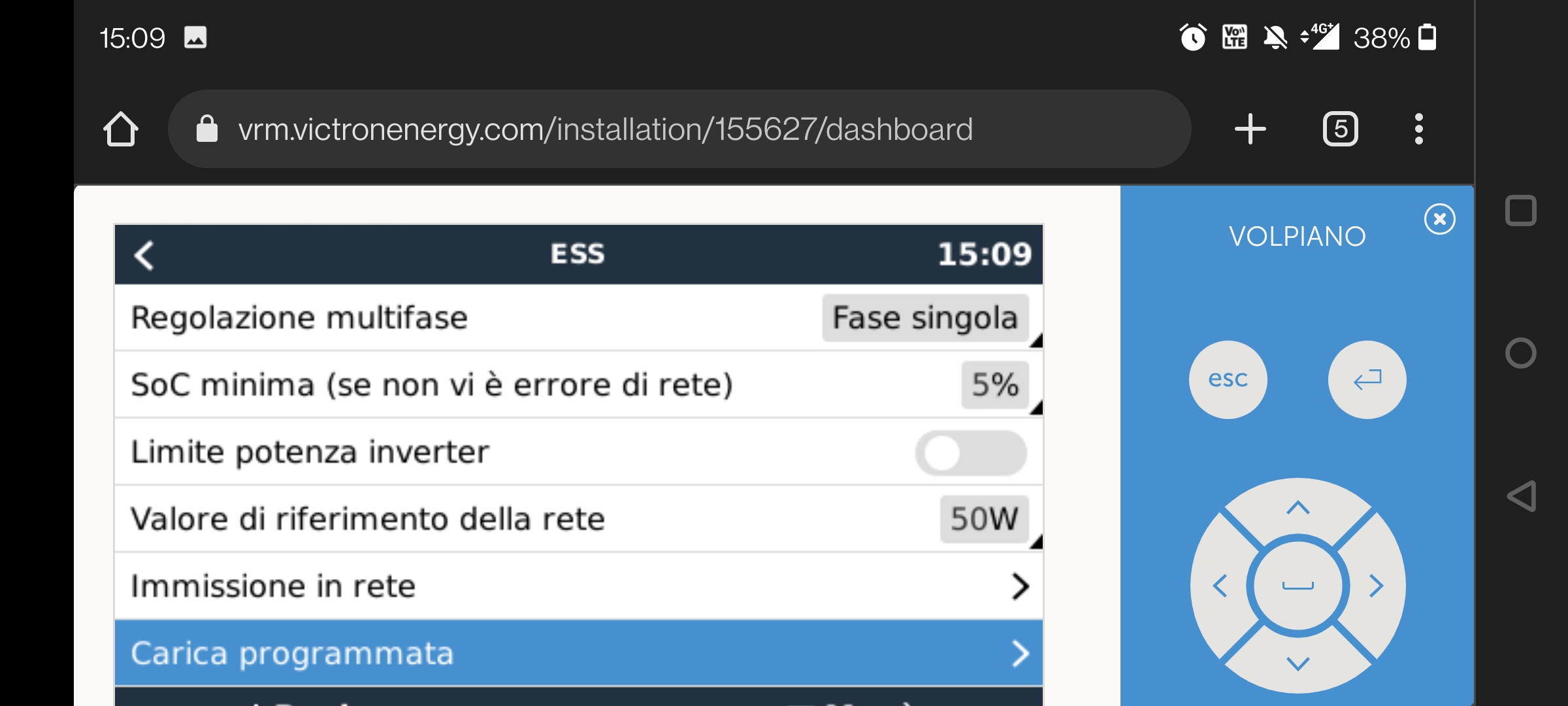
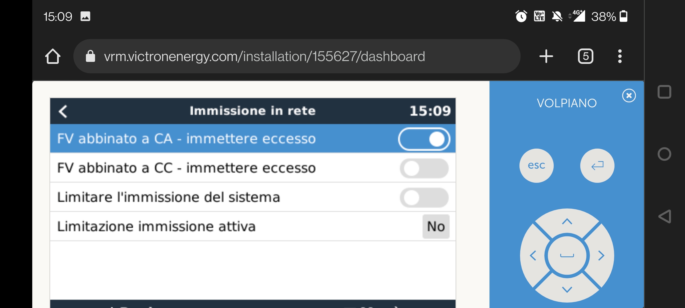
What is your settings in "Grid feed-in" option in ESS settings?
Do you have "DC-coupled PV-feed in excess" selected?
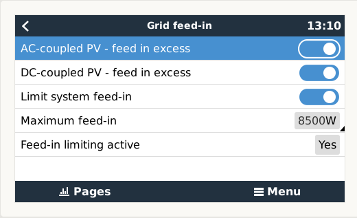
AC pv on , DC pv off . I am not allowed to inject DC, only the excess AC. I would like to use DC pv for battery charging and for loads
Selecting AC-coupled PV ON, does not make any sense since you do not have AC-coupled PV inverter.
Selecting DC-coupled PV OFF is the reason why your PV is used only to charge your battery.
If you want to use your battery for loads you have to present a load for the battery to be used on.
Since you do not have any AC-out load the battery has nothing to supply load to.
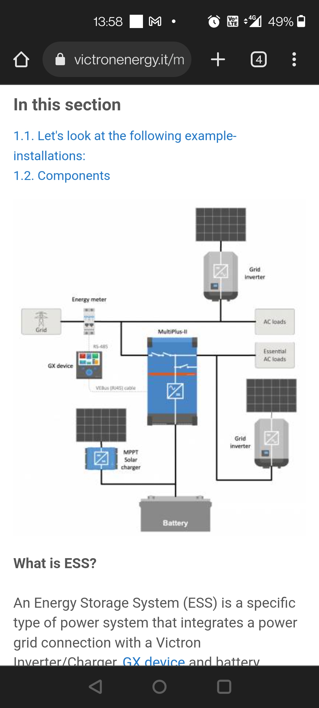
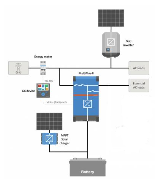
If your setup looks like this.
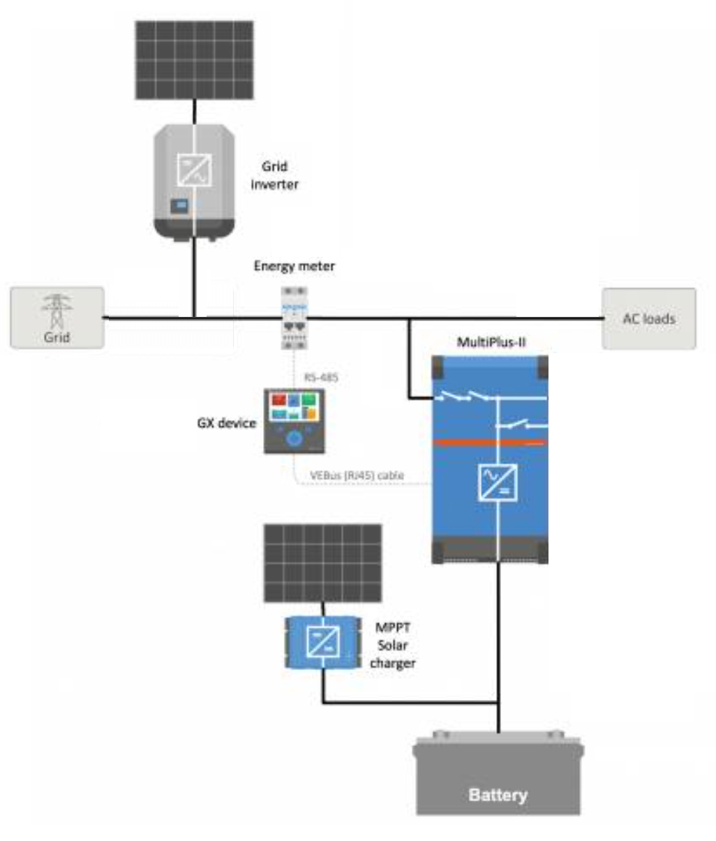
it will not work properly.
Problems.
1. ESS does not work properly because it does not know what is happening at grid connection.
2. MPPT is charging only a battery and this energy does not have anywhere to go.
It shoul look like this.
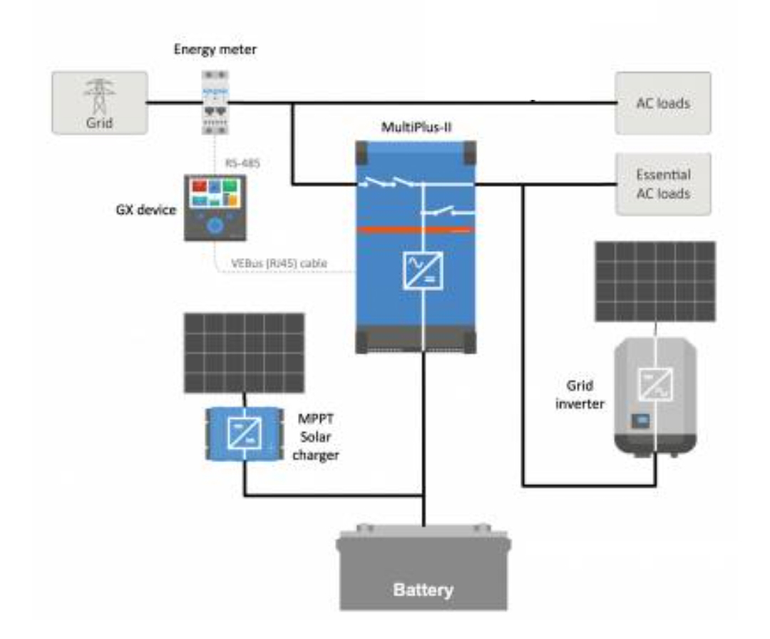
1. ESS can control your "self consumption and storage" function of the system.
2. Your Fronius will work when grid is down.
3. Battery power can be properly used by ESS system for critical house loads.
4. External to the battery SOC measurement is needed if this system is not to be interrupted by BMS all the time when battery gets to 100%SOC.
sorry maybe I can't explain myself well.
my ess is working fine as you can see now both the PV DC and the battery are powering the loads but this only happens when there is a lot of load. When Energy Meter sees input on the grid, the load is taken by the fronius and the PV DC is reduced to the charge value set on the dvcc.
I cannot move the fronius, it must remain connected upstream
@lucadea1985@gmail.com
I ask again.
Is a DC-coupled PV allowed to feed the greed or not?
If it is not allowed as you stated before there is no way for energy from DC-coupled PV to travel trough EasySolar's AC-in connection with the grid.
Now you show that it is feeding the grid.
Which one is it?
Show your ESS settings.
Why Fronius cannot be AC-coupled?
For the grid authority there should be no difference between Fronius connected to AC-in or AC-out.
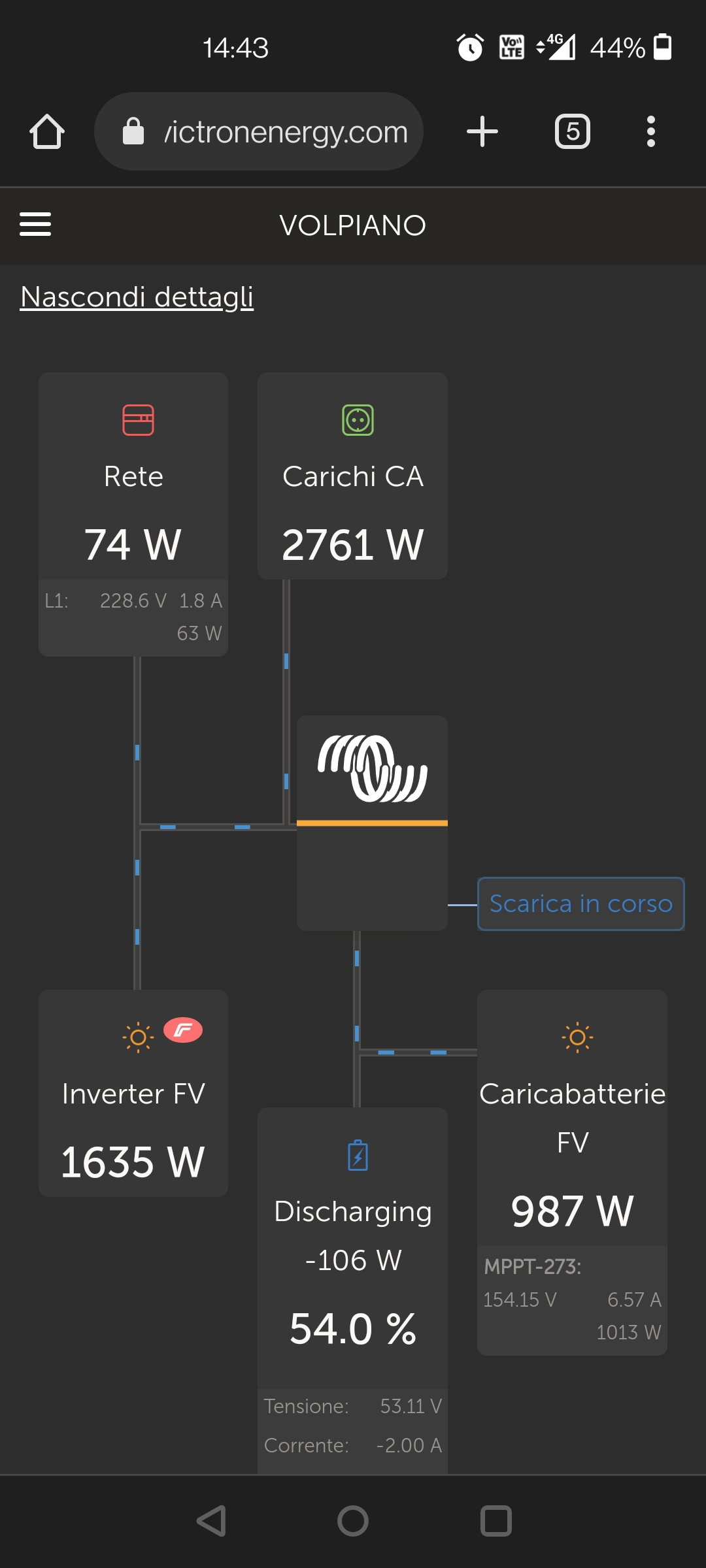
thanks for your help. The PV DC is not enabled to inject into the grid but manages the request on the load. as you see in the screenshot I sent earlier, the PV DC is powering the load aided by the battery because the Energy Meter has reached its reference limit of +50 watts it does not inject into the public grid. In Italy we have regulations and I cannot move the fronius, when the grill is missing the fronius must switch off.
My ess:
The PV DC is not enabled to inject into the grid but manages the request on the load. as you see in the screenshot I sent earlier, the PV DC is powering the load aided by the battery because the Energy Meter has reached its reference limit of +50 watts it does not inject into the public grid.
It is very convoluted system and it will never work properly.
I am surprised that the GX can make "heads or tails" with the data you are providing. Especially the ET112 behind Fronius and not counting its production on the grid connection.
I wonder what did you tell GX, where this ET112 is located and what is actually measuring?
In Italy we have regulations and I cannot move the fronius, when the grill is missing the fronius must switch off.
Fronius connected to the grid has to turn off (be disconnected) everywhere, not only in Italy, but when you connect Fronius at the AC-out of EasySolar-II and grid is gone, Fronius is disconnected from grid by way of two relays at the AC-in of ES-II. In this situation the ES-II is disconnected from the grid and is generating micro-grid and Fronius can continue to work. ES-II is working in OFF-grid mode than and I assume the OFF-grid systems are legal in Italy.
yet it seems not to have done anything strange. I followed the manual box. The production of fronius is detected via the LAN, and Victron fronius dialogue between them. The GX therefore has all the parameters or production fronius, PV DC output which is integrated into Victron et112 and with the flow from the counter calculating the watt from fronius. As a first test I put et112 upstream of the entire system but not charging an correctly when the fronius was active. Moved between fronius and instead load counts properly. For the fact of moving the fronius can not and will not do it because it is a system certificate in this way and there are electric company meter that monitors the production. In case of failure to the grid I, however, the PV DC operating.
yet it seems not to have done anything strange.
If it did everything right you would not come here looking for help.
The production of fronius is detected via the LAN, and Victron fronius dialogue between them. The GX therefore has all the parameters or production fronius, PV DC output which is integrated into Victron et112 and with the flow from the counter calculating the watt from fronius.
There is no option, in GX settings, where you can specify Fronius position in front of ET112. Therefore GX has no clue where to calculate Fronius production.
For the fact of moving the fronius can not and will not do it because it is a system certificate in this way and there are electric company meter that monitors the production. In case of failure to the grid I, however, the PV DC operating.
Sorry but I do not understand why you bought the EasySolar-II if, based on what you are saying, you are not allowed to have OFF-grid system. EasySolar-II is a part of the OFF-grid system.
I had installed like this scheme but the values were not detected correctly. The energy of the fronius was added to that detected by the et112... the only way to see the correct values was to move et112 after the fronius. The energy of the fronius is detected and used in the correct way, the problem is the reboots of the 100% battery system and the non-use of pv dc surpluses for loads when the fronius injects its surplus to the grid. an off grid system I can install but I can not touch or modify the existing and certified fronius. fronius must stay on ac in, everything else I can change it. what would you do? Thank you
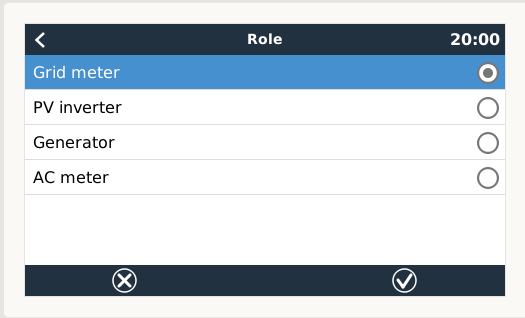
In the GX controller,
where is location of PV inverter specified?
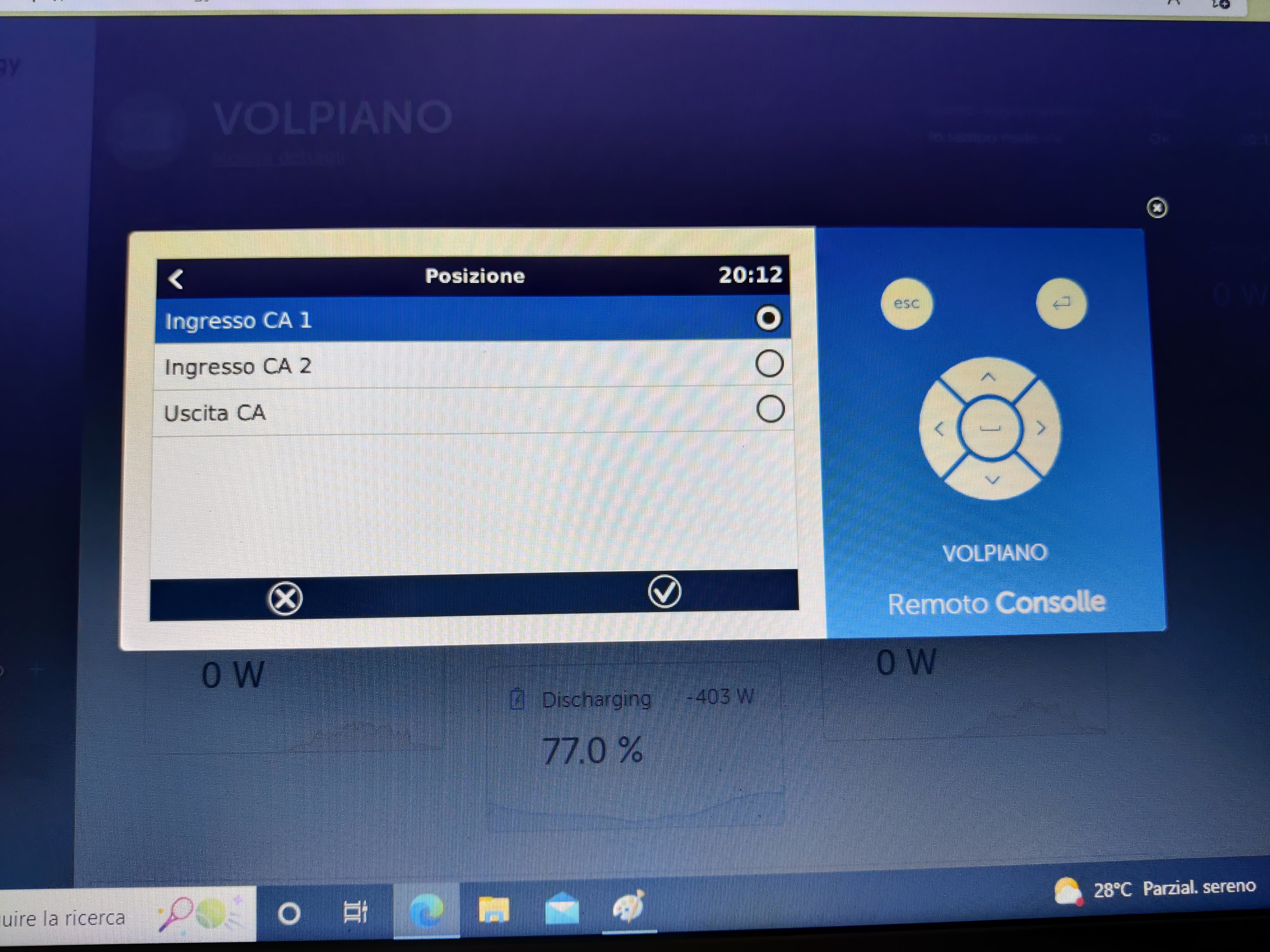
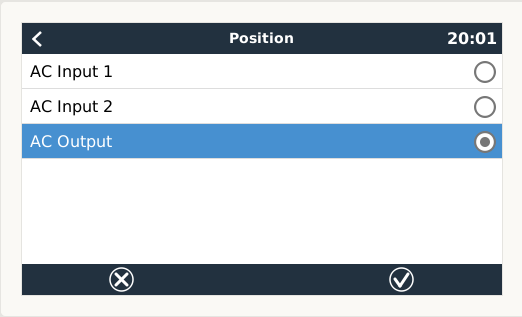 where you have location of ET112 specified
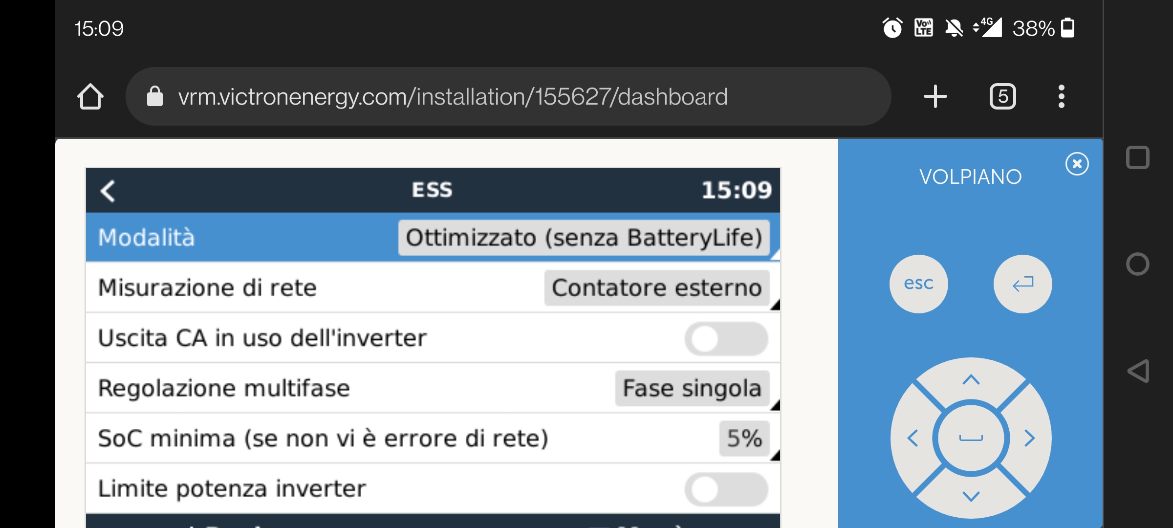
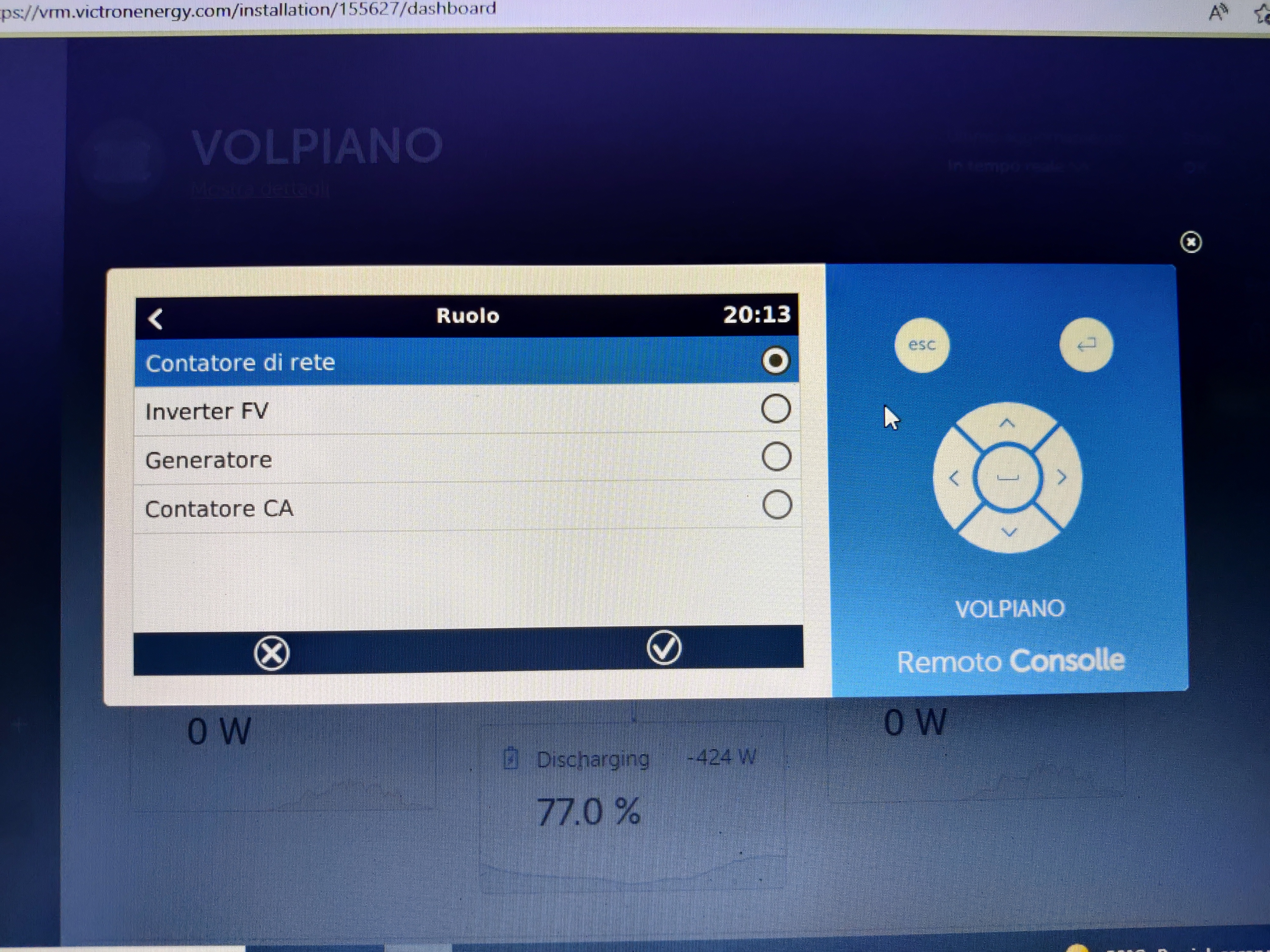
Queste le mie impostazioni
@lucadea1985@gmail.com
Your settings:
Fronius connected at AC-in and ET112 as a grid meter.
As a result of those settings.
ET112 cannot be placed between Fronius and AC-in.
My sugestion is for you to connect loads to AC-out and see how energy will flow in your system.
ok I'll try. I update you. Thank you very much
I lowered the charging voltages so that the bms doesn't stop charging and the system doesn't restart anymore. Thanks for the tip.

There remains the problem of the ft dc which does not cover the load requirement when there is grid injection from the fronius
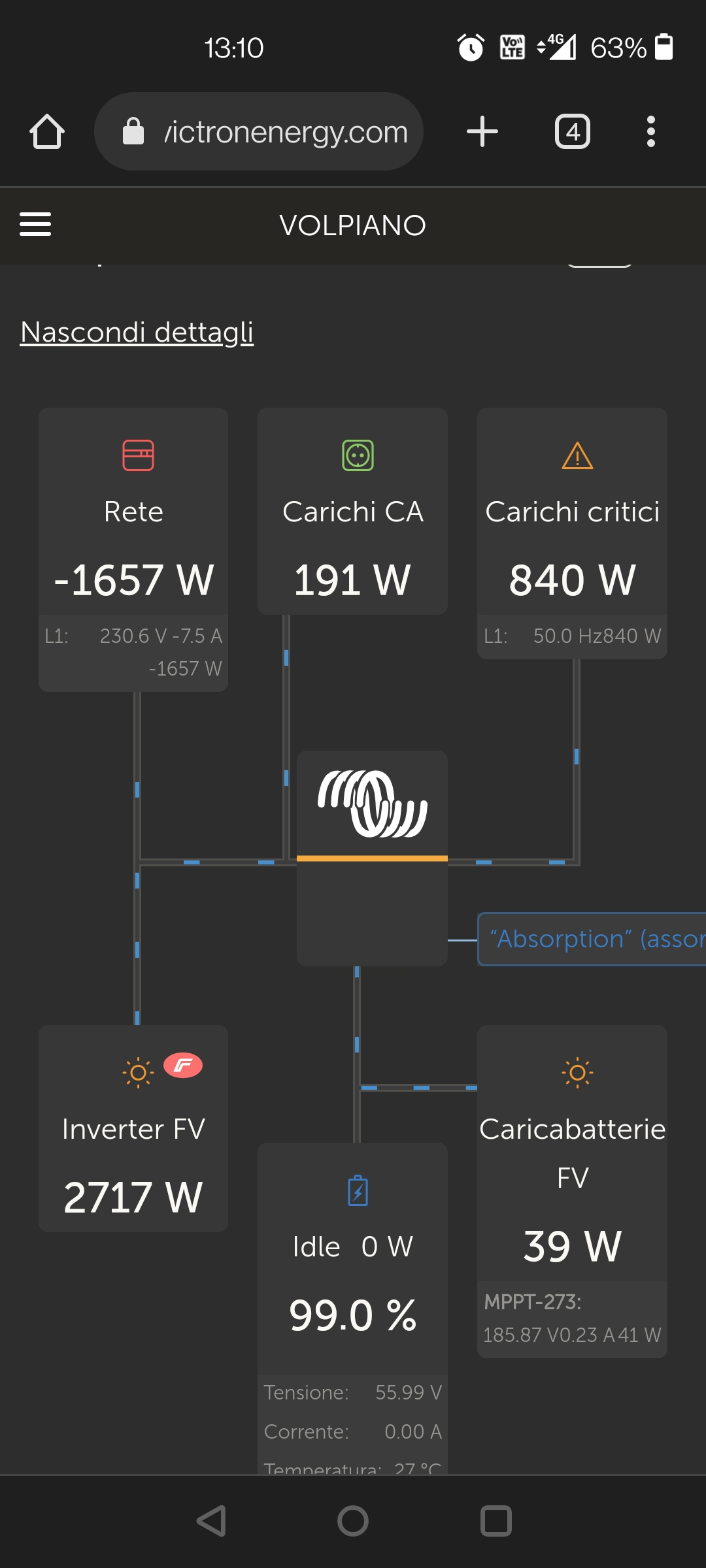
I was wrong, the Energy Meter is upstream. I moved the major loads to AC output out critical loads but as you can see in the screenshot the DC PV does not cover the loads, it is weakened when the battery is charged and the energy of the fronius is used. Instead, I would like the loads to be covered by the pv cc and the fronius completely injected into the grid. It is not possible to do it ?? thank you all
I am not sure but its logical to use Fronius energy first to power the loads because its DC-AC conversion is more efficient that MP-II's
Try not telling the system GX that you have Fronius connected at AC-in and install ET112 behind it. GX will use only DC-PV and battery and when its not enough it will pull energy from grid and when at that moment Fronius is producing it will be the source of the energy "from grid".
To be honest I would not worry abut DC-PV being throttled down.
now works. I had to set inverter / caricabatterie to grid meter setting in the ess menu.
but now I no longer have the critical loads output and I have no UPS function when the grid is missing.
Now sytem GX does not know what is happening at grid point because power is measured at MP-II AC-in point. There is now no difference between loads and critical loads. This is why all loads are just loads. Also GX is confused where is Fronius connected. Missing UPS function is probably the result of wrong information being fed to the system.
Hello marekp, I had the wrong AC output ... the UPS function works correctly and now everything is connected on critical load but even so it doesn't do what I want. It is true that the energy from the fronius is more efficient but he also made a DC AC conversion, similar to what my easysolar would do ... the energy I would like to use for the loads would be free because otherwise my PV DC would be reduced to 0 watts. I think the problem is the fronius injection because the GX does not activate the PV DC until the 50 watt grid setup is exceeded, once this is exceeded, the PV DC also intervenes for the loads. Normally, however, he sees 1500/2000 watts of injection from the fronius and does not let me intervene the PV DC. If I disable the fronius al gx I lose the efficiency of the system as the battery is discharged even when I have a lot of surplus from the fronius ... I don't like it that way
@lucadea1985@gmail.com
You have to decide if you want all energy from Fronius to go to the grid. If you do Fronius has to be outside of your system.
You could turn on DC feeding the grid but limit the amount of energy fed to the grid to less than 3kW (Your Fronius max).
This way Fronius and DC PV will be used at max possible.
If you cannot do that the system will work as it is now.