Anyone come across a solar radiation sensor with output voltage proportion to incoming insolation. Would like to record the values with the Venus GX.
asked
Solar radiation sensor
UPDATE - We now have a resolution!
The Si-RS485TC Series solar irradiation sensor and optional wind and temperature sensor are now natively supported by GX devices.
See here for more information on wiring, configuration, and output:
Yes, it's called a solar panel! :)
Seriously though, sensors like that are just miniaturized PV modules (the same chemistry) with a constant load or resistor across them. The voltage output is then proportional to the light intensity.
Often, a small solar panel is used as the sensor in DIY arrangements.
Someone in this community did do something with the Venus' temperature inputs to measure insolation. I'll hunt around for the link and post it here.
I am not familiar with the term "incoming insolation", would someone please explain.
I'm using a Solar Irradiance/Panel Temperature sensor from IMT Solar for my diversion load project. It returns irradiance in W/Meter Squared and panel temperature in degrees C. They are available with 0-5V, 0-10V, or 4-20mA outputs. Don't know if it could interface with the Venus GX, just thought I would mention it.
Pat
also called irradiance see https://en.wikipedia.org/wiki/Solar_irradiance , I'll look up that sensor thanks
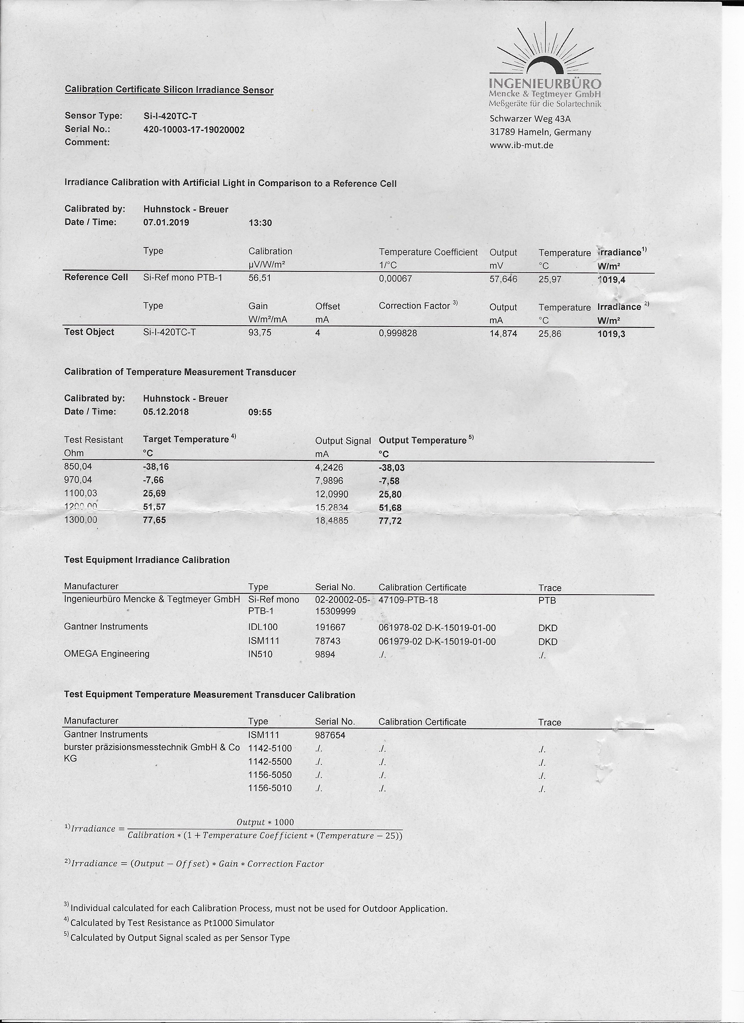
Thanks for the info. The IMT Solar sensor model I am using is Si-I-420TC-T.
Pat
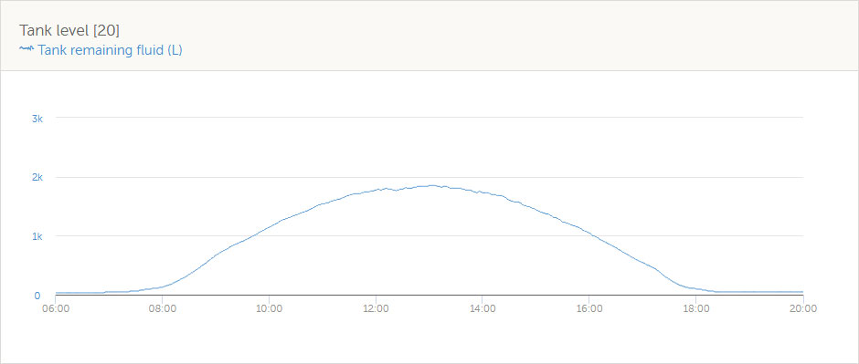
I have a small solar panel (3W for 6V batteries, about 0,3A Imp) connected to the Venus GX tank level input, together with a 2,2 Ohm resistor in parallel. The Tank Level input is configured for 0-180 Ohm tank level sensors. The graphic below looks as one would expect a solar radiation curve.
The calibration could be done in comparison with the actual solar generator. One easy option for calibration is that the tank level indicates the same number as the PV output, for example 1800 liters means 1800W. Adjust the tank capacity till PV yield has the same number as Tank Level. Like this it is easy to read how much PV power is available versus how much is actually used.
The calibration with the PV generator should be done during "bulk" phase, when the charge regulator is not reducing PV output.
If you prefer the figure representing solar radiation as W/m2, do the calibration above first, then divide the tank capacity by your kWp solar generator size. Maybe add something for the reduced efficiency of the PV panels at higher temperatures than 25 C. Or do the calibration when the PV panels are at 25 C on a cloudy day.
Another way of calibrating is to measure the short circuit current of a PV panel and compare to its Isc maximum current according to its label. Be aware, small panels (2W, 5W etc) which could be used as sensor may be very inaccurate in terms of label and real performance, better use a big "serious" panel for calibration if you want more precision.
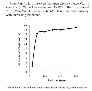
Interesting, I like where you are headed. You might consider measuring the Open Circuit Voltage (Voc) of the panel; it is directly related to the solar irradiance the panel is receiving. You can then compare this to the STC ratings of the panel and compute the wattage output for any given any sun condition. That's what, I believe, the IMT Solar sensor does.
Pat
Voc is related to temperature, not the amount of sunlight
Current is related to the amount of light, that's why Tilo's solution works with the resistor in parallel.
You are correct, Voc measurements do need to be temperature compensated. However, Voc is linked to solar irradiance.
For this to work the following conditions must be met:
1. No loads can be attached to the measurement panel.
2. A very precise voltage measurement device must be used.
3. A panel temperature measurement device must be provided.
3. A means of mathematically calculating W/M2 from the voltage measurement and Voc temperature coefficient must be provided.
4. The sensor device must be calibrated using STC test equipment.
In the graph shown below there is a large jump in Voc between 0 and 100 W/M2 and then the Voc increases linearly, in small increments, with Irradiance.
Also below is the Calibration Certificate for the sensor I am using.
Pat


Why would you do it that complicated when you can just use current measurement?
I mainly included the "how-to" for anyone that might want to DIY a solar irradiance sensor. Since I bought a sensor that does all those things, it wasn't that complicated.
The goal of my off-grid project is to use actual solar irradiance measurements, in an unattended/automated way, to directly control a diversion load. I have a prototype that proportionally controls the power to a resistive heating element from 0-25A at 120VAC. If the sun goes behind a cloud it reduces the amperage to a level the panels can support and raises it when the sun comes back out; even if the panels are also bulk charging the battery. The goal is to use any excess power available no matter what else is going on with the main system. So far it works.
Is it economically practical, probably not. But it is an interesting project.
Pat
Nearly all the answers I need. But being a newbee in Victron's maze, I would appreciate further guidance to have the irradiation info on VRM.
I think someone wrote here that Victron was considering a special accessory for that, probably to be plugged into CCGX VE-CAN or somewhere else. No new as of now.
For that limited purpose something like a Si-RS485TC-T or 2T should do (I shall check with imt-solar) but how to feed it into CCGX, to have the result on VRM? Can Tank Sender adapter?
For some years I had a voltage logger (EL-USB) measuring the voltage between the ends of a resistor fed by an old 20Wp. setting was done by adjusting the R value. But it was cumbersome (offline management, no temp correction...). A solution throu CCGX and VRM wouls be fine!
Thanks
Good news: there is (beta) support for a standard sensor, read here:
https://community.victronenergy.com/questions/31299/venus-os-v24034-available-for-testing.html?
To Guy Steward,
Nearly all the info I need. Just not to lose time whan I purchaseans install a Si-RS485 TC -T
- Is the output cable from the sensor nude or fitted with a RS485 plug?. That would meant I should purchase a RS485 femele to female plug. On the connection drawings you send it looks as if both sensor cable and RS485 to USB cable have to be denuded and connected in some sort of connecting box. Am I right?
- About the version of Venus OS, on VRM I have for Gateway, firmware V 2.52 is that OK?
Not in my mountain yet: too much snow and the lifts are closed.
Good luck to you and all colleagues!
Lionel SEYDOUX
Hi @Lionel SEYDOUX,
-RS485 is not a 'plug' standard/description - it is a standard related to the electrical characteristics of drivers and receivers in serial communication systems.
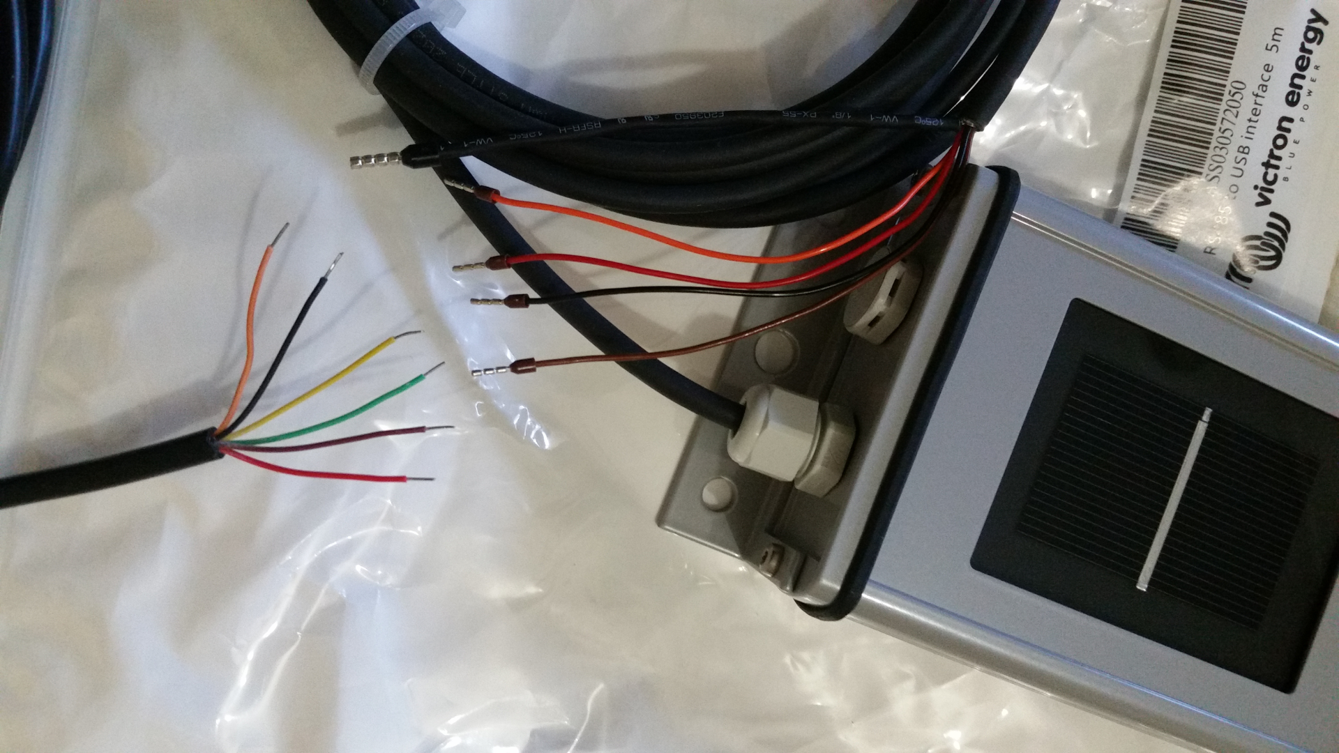
-Both the IMT Si-RS485TC Series irradiance sensor and the Victron RS485 to USB interface cable come with bare/stripped wire ends - see photo below;

-You can join the wires together directly with a single terminal block if you have enough length. But if you need more length, simply use an appropriate specification data cable to extend it and use two terminal blocks.
As the wires are so small/fine, its a good idea to use small bootlace terminals on all ends.
Also include a small inline fuse (~1A max) on the DC power supply.
-Venus OS FW v2.52 is fine, the update was introduced in FW v2.40.
Best of luck with your install.
Good day,
Is the Si-RS485MB Series solar irradiation sensor also compatible with the GX devices?