question

bertolucci avatar image
bertolucci asked

Mehrere Temperatursensoren DS18B20 verwenden?

Servus miteinander,

ich habe in meinem Womo einen Raspberry PI 4 verbaut und den bis jetzt über NodeRed am laufen gehabt. Darunter auch 3 DS18B20 Sensoren.

Da mein bisheriges Votronic Equipment nicht sehr "kommunikativ" war bin ich jetzt auf Victron-Technik (BMV 712 + Solarregler) und Venus umgestiegen und das macht riesig Spass.

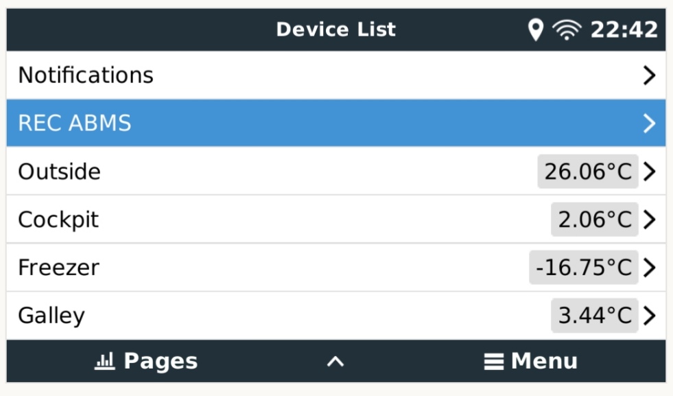
Allerdings komme ich als Neueinsteiger im Venus-System an meine Grenzen. Einen Temp-Sensor konnte ich einbinden, die Raspi-Temperatur wird mir auch angezeigt. Die weiteren Sensoren bringe ich nicht mit dazu. Wenn ich testweise meine alte SD-Karte mit dem klassischen RaspiOS einstecke funktionieren alle Sensoren.

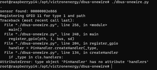
Hat jemand einen Tipp für mich, wie ich mit der aktuellsten Venus-Large Version mehr als einen DS18B20 am Bus zum laufen bringe?


Vielen Dank und Gruss

Robert

Temperature Sensor
2 |3000

Up to 8 attachments (including images) can be used with a maximum of 190.8 MiB each and 286.6 MiB total.

9 Answers
johanndo avatar image
johanndo answered ·

So ported the service to the latest VenusOS / Python 3

included the w1therm module in the path.

Extract the zip file on the Venus root (files are added to )

/opt/victronenergy/dbus-onewire/*

/opt/victronenergy/service/dbus-onewire/*

Prerequisites: enable 1Wire in /u-boot/config.txt

dtoverlay=w1-gpio,gpiopin=4

dtoverlay=w1-therm


....

copy from raspbean system w1-gpio.dtbo into /u-boot/overlays/

you can copy all overlays from raspbean into this directory if you plan do use other gpio protocols / devices. I did not provide the overlay dto in the zip, as this may be hardware / system board dependent, I have a rPi4-4GB older revision.


check, your sensors are working

ls /sys/bus/w1/devices

You can run the service manually by calling it from the command line, it will start automatically on reboot usually, otherwise run the run command in the dbus-onewire service directory.


Configuration

you can set the sensor ID by using dbus-spy, go to com.victronenergy.settings and scroll down to Settings/Temperature/<serial>/DeviceInstance, enter a unique ID 1...n for each sensor, you can also enter a /CustomName here or do this in the GUI.

That's it basically, enjoy and let me know if it works for you.


you can see if it works by looking into the logfiles

cat /data/log/dbus-onewire/current

cat /data/log/dbus-systemcalc-pi/current

look in dbus-spy too, you should a service per sensor

com.victronenergy.temperature.onewire-<DeviceId>

and also settings per sensor in

com.victronenergy.settings

dbus-onewire.zip


dbus-onewire.zip (177.3 KiB)
1 comment
2 |3000

Up to 8 attachments (including images) can be used with a maximum of 190.8 MiB each and 286.6 MiB total.

berteh avatar image berteh commented ·

Awesome, thanks all is working as it should :)

0 Likes 0 ·
Stefanie (Victron Energy Staff) avatar image
Stefanie (Victron Energy Staff) answered ·
2 |3000

Up to 8 attachments (including images) can be used with a maximum of 190.8 MiB each and 286.6 MiB total.

bertolucci avatar image
bertolucci answered ·

Servus Stefanie,

vielen Dank für die schnelle Antwort und die beiden Links.

Ich kannte die beiden Themen bereits und habe mich da erfolglos durchgehangelt. Deine Mail habe ich zum Anlass genommen und die dbus-i2c.py Datei noch einmal Zeile für Zeile durchgesehen. Ich habe alle Änderungen so durchgeführt, wie sie bei der Datei aus dem zweiten Thema zu erkennen waren (geändert durch Jonny als Vermerk).

Leider erfolglos. Beide Sensoren wurden erkannt und waren im Verzeichnis w1_bus_master1 mit eigenen Verzeichnissen der jeweiligen Sensorkennung vorhanden.

Allerdings war kein einziger Temperatursensor und auch die PI-Temperatur in der Remote Konsole als Eintrag vorhanden. Auch NodeRed liess sich nicht starten.

Lasse ich beide Sensoren eingesteckt, aber verwende wieder die ursprüngliche dbus-i2c.py erscheinen in der Remote Konsole zwei graue TEMP-Felder ohne Temperaturanzeige und Node-Red lässt sich immer noch nicht starten.

Entferne ich dann den zweiten Sensor funktioniert alles einwandfrei. Es erscheint die Temperatur des ersten DS18B20 Sensors sowie die RPI-Temperatur und auch Node Red funktioniert wieder einwandfrei.


Hätte noch jemand einen Tipp für mich, auf was ich noch schauen muss? Müssen auch andere Dateien geändert werden?

Vielen Dank und Gruß

Robert

2 |3000

Up to 8 attachments (including images) can be used with a maximum of 190.8 MiB each and 286.6 MiB total.

johanndo avatar image
johanndo answered ·

img-20220422-224301.jpgimg-20220522-154351.jpg
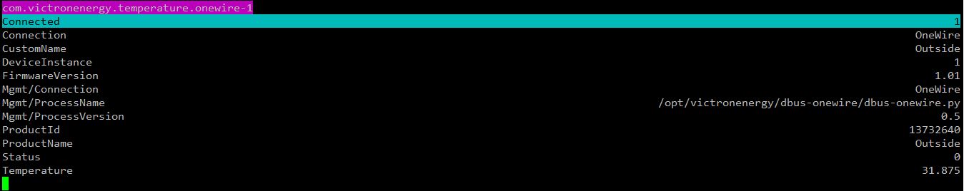
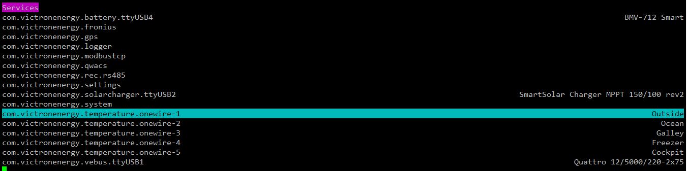
Ich hab mal einen eigenen Treiber geschrieben und bis zu 6 DS18B22 anbinden können, allerdings musste ich den pullup dafür halbieren und die Sensoren aktiv mit Strom versorgen.img-20220602-121909.jpg


2 |3000

Up to 8 attachments (including images) can be used with a maximum of 190.8 MiB each and 286.6 MiB total.

bertolucci avatar image
bertolucci answered ·

Servus,

das schaut sehr gut aus. Externe Stromversorgung für die Sensoren oder auch die Halbierung des Widerstands wären kein Problem ;-)
Könntest du mir mit dem Treiber etwas weiterhelfen? Funktioniert das auf einem aktuellen System oder braucht es noch zusätzliche Anpassungen?


Vielen Dank für deine Unterstützung und Gruß

Robert

2 |3000

Up to 8 attachments (including images) can be used with a maximum of 190.8 MiB each and 286.6 MiB total.

johanndo avatar image
johanndo answered ·

dbus-onewire-details.jpgSensor details im Service


Settings, Zuordnung physikalische Adressen zu ID und Namen der Sensoren,
Man kann sie Umbenennen und eigene ID zur Sortierung und eindeutigen Zuordnung im VRM vergeben, der dienst sucht erst in den Settings und registriert dann unbekannte Sensoren, bekannte bekommen die alte ID und Namen.

dbus-spy.jpg


So sehen die Dienste pro Sensor aus:
dbus-spy.jpg


2 |3000

Up to 8 attachments (including images) can be used with a maximum of 190.8 MiB each and 286.6 MiB total.

berteh avatar image
berteh answered ·

JohannDo this looks like an awesome code as it searches for all connected 1wire sensors but not having to hardcode ID's in a script.

But the code does seem to work on VenusOS 2.80+ due to it only using python3 is there any chance you could update your code to work with VenusOS 2.80/python3


Thanks :)

5 comments
2 |3000

Up to 8 attachments (including images) can be used with a maximum of 190.8 MiB each and 286.6 MiB total.

johanndo avatar image johanndo commented ·

Copy the new victron libraries from another python service on your OS to the include subfolder /velib_python

You can change the line in start-onewire.sh

exec /usr/bin/python /opt/victronenergy/dbus-onewire/dbus-onewire.py

to

exec /usr/bin/python3 /opt/victronenergy/dbus-onewire/dbus-onewire.py

That may do the trick.

0 Likes 0 ·
berteh avatar image berteh johanndo commented ·

dbus-onewire.zip

Yeah, I did that, then the issue becomes about inconsistent use of tabs and spaces in indentation, when I fixed that, I got errors about the print statement not being correct, aaand after I fixed that i got naming errors: NameError: name 'PinHandler' is not defined


I'm not a coder SO i was at a loss after patching those and also copying over the new libraries as you said.


ps there is also a few errors in the dbus-onewire.py I found also

sys.path.insert(1, '/opt/victronenergy/dbus-onewire/ext/velib_python')

I had to change this to:

sys.path.insert(1, '/opt/victronenergy/dbus-onewire/velib_python')


gobject did not want to import so I found this in another dbus script here on the community:

from gi.repository import GObject as gobject

and I was unable to install smbus (1) but smbus2 did install so I changed the import for that as well:

from smbus2 import SMBus, i2c_msg

and then I had to change the bus = statment to

bus = SMBus(1)


tl;dr I attached my poorly hacked together file for reference on how not to fix stuff :D


0 Likes 0 ·
dbus-onewire.zip (2.7 KiB)
johanndo avatar image johanndo berteh commented ·
You can comment out the smbus thing, it is for I2C sensors, i had them included into the script for BME280 temp, humidity, pressure, but removed them later. sorry, Did not saw the include of the library is still there. The path is correct on my system, probably problem downloading the folder structure. The I2C support was commented out and later deleted, as I have no I2C temp sensors at the moment in my setup and I want to make a separate driver for other I2C devices, like current sensors and A/D converters.
0 Likes 0 ·
johanndo avatar image johanndo berteh commented ·
All lines with print statements are for debugging purposes only and can be safely commented out, you can run the script on the console instead as a service (stop the service first), and then you would see the printed data on the shell window when the code is executed. You can replace the print statements with the new python3 print syntax if you want to.


All python services can run in the console and be analyzed / traced that way without digging in the log, quite convenient.
0 Likes 0 ·
berteh avatar image berteh johanndo commented ·

I think I've mended most of the things and I've been running it from console, not from starting the service, but now this is the issue I'm facing:

1655392875886.png


here is the most current code I'm using:

https://pastebin.com/mQGvHyxi


0 Likes 0 ·
1655392875886.png (24.1 KiB)
johanndo avatar image
johanndo answered ·

I use an older Venus version, had to adapt it to the old python I recall, but shouldn't be a problem to change the few lines of code I think.

I am still on 2.42 that is running on the old python, so and cannot test on pytthon 3 atm.

2 |3000

Up to 8 attachments (including images) can be used with a maximum of 190.8 MiB each and 286.6 MiB total.

johanndo avatar image
johanndo answered ·
  1. The Meta class is there in PinHandler and the constructor creates the array, seems there is a problem creating it, as it doesnt find 'handlers' It tries to create a type 1 (D18B20) handler, so the sensor is recognized. You may print the parameters you provide to the constructor to see if something is missing or wrong. You may add 2 print statements inside of the constructor to see it is actually been called and that it creates the empty structure to monitor the sensors it finds.

  2. class HandlerMaker(type):
  3. """ Meta-class for keeping track of all extended classes. """
  4. def __init__(cls, name, bases, attrs):
  5. if not hasattr(cls, 'handlers'):
  6. cls.handlers = { }
  7. else:
  8. cls.handlers[cls.type_id] = cls
  9. .....

The HandlerMaker and its constructor should be called when you instantiate a new PinHandler, and then create this handlers structure or assign the type to it.

  1. class PinHandler(object):
  2. product_id = 0xFFFF
  3. _product_name = 'Generic GPIO'
  4. dbus_name = "GPIO"
  5. __metaclass__ = HandlerMaker


2 |3000

Up to 8 attachments (including images) can be used with a maximum of 190.8 MiB each and 286.6 MiB total.

Related Resources

Victron temperature sensor disambiguation table - which product supports which sensor