question

rns avatar image
rns asked

How to configure victron transfer switch

In the next phase of my victron setup I plan to order a transfer switch. In the preperation I try to finde documentation / configuration video / training video in how to configure the transfer switch.

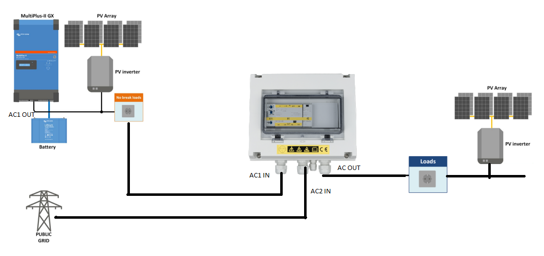
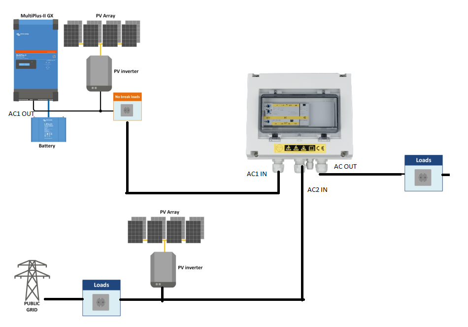
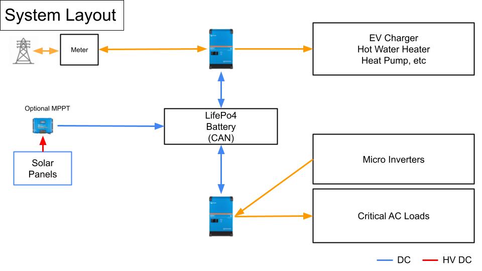
In my setup I have a multiplus II with a battery and on AC1 OUT I plan to connect my entire electricity board and PV panels.


Whe the battery becomes too low, the transfer switch should switch back to the grid (PV panels should stay on the multiplus AC1 OUT)

I want to understand and know how to set this up.


Multiplus-IIswitch
2 |3000

Up to 8 attachments (including images) can be used with a maximum of 190.8 MiB each and 286.6 MiB total.

11 Answers
rns avatar image
rns answered ·

can anyon help me or direct me to documentation ?

2 |3000

Up to 8 attachments (including images) can be used with a maximum of 190.8 MiB each and 286.6 MiB total.

sharpener avatar image
sharpener answered ·

I don't think you need a transfer switch to achieve this. I have just installed a MultiPlus II 5kVa with the whole house and a 3.6kW PV inverter all connected to AC Out1. The batteries are charged from the PV and supply the loads until they are exhausted, then the system reverts automatically to the maiins, it is all explained in the ESS manual.

2 comments
2 |3000

Up to 8 attachments (including images) can be used with a maximum of 190.8 MiB each and 286.6 MiB total.

rns avatar image rns commented ·
You are completely right for your situation but my situation is a bit different. Connected on the grid I'm limited to 5kW PV installation on a single phase. Upgrading to 3 phase would require me to shift to a digital meter while I have now still a meter that can turn back. I wanted to add more PV panels so I can start heating with my airco but and prepare for an electric car. So I wanted more solar panels what I can't connect to the grid. Only option is using the Multiplus as an off grid solution and when my battery is getting low I transfer back everything except the extra solar panels. So to do this step automatically I need something like the transfer switch.
0 Likes 0 ·
shaneyake avatar image shaneyake rns commented ·
Victron does make the RS450/100 MPPT, it is great for these situations. You can run 400V dc from your panels to the MPPT so you can install small cables and go long distances if needed.
0 Likes 0 ·
marekp avatar image
marekp answered ·
2 |3000

Up to 8 attachments (including images) can be used with a maximum of 190.8 MiB each and 286.6 MiB total.

sharpener avatar image
sharpener answered ·

What country are you in? In the UK I am limited to 16A max feed-in and the DNO has insisted I restrict the inverter power of the MP II to 3.7kW in addition. I plan to add extra PV (also for a heat pump and EV), I will put this on the DC side using an MPPT so it does not result in an increase to these figures. Can you do the same? It is also a bit more efficient getting the PV power into the batteries this way.

1 comment
2 |3000

Up to 8 attachments (including images) can be used with a maximum of 190.8 MiB each and 286.6 MiB total.

rns avatar image rns commented ·
A direct DC inverter would indeed be allowed but the distance from the solar panels to the battery makes it very difficult/impossible. Small microinverters makes live easy at this moment. Can just throw a few solar panels on the shed. Even that it is less efficient, it compensates that I can use that roof. (will do it safely by connecting 6mm2 cable between the main braker panel and the shed braker panel with brakers and eart leak disconnect so I can't overload one circuit since this introduces lokal production on the cable).

A also want to add more PV's on my flat roof but not a clean option anymore to bring the DC cables to the battery. Also here I have a braker box nearby (installed when installing the arico unit I use as heatpump in winter).

The DC option I will use when I find some cheap solar panels for on the carport but they get only sun late in the afternoon so not worth spending money for expensive new panels. (certainly now when there is a rush for PV panels and inverters )


But thanks for the tip. Would work.

0 Likes 0 ·
Matthias Lange - DE avatar image
Matthias Lange - DE answered ·

There is nothing to configure at the transfer switch. It switches automatically between two AC inputs depending on which is available.

If both inputs are available then input 1 had priority over input 2.

5 comments
2 |3000

Up to 8 attachments (including images) can be used with a maximum of 190.8 MiB each and 286.6 MiB total.

rns avatar image rns commented ·
Ok thanks for this feedback. This looks like it will always completely drain the battery and waiting for a battery disconnect before it will trip. Was hoping I could also stear this a bit.

Could I make it a bit more intelligent ?

0 Likes 0 ·
marekp avatar image marekp rns commented ·

@rns

Battery will be drain to the level set in ESS setting. Not completely. Of course if you set that level to 0% it will be "completely"

P.S. Can you tell us what you mean by "transfer switch"?

0 Likes 0 ·
marekp avatar image marekp commented ·
@Matthias Lange - DE

Judging from the initial post he has MP-II with only one AC-in.

0 Likes 0 ·
rns avatar image rns commented ·

I'm looking at this : https://www.victronenergy.nl/transfer-switches/ve-transfer-switch

can automatically switch between two AC inputs. One would be the grid and one would be my multiplus II including the PV part. If I understood correctly in my case the multiplus should be on AC1 and the grid on AC2 so my multiplus gets priority above the grid

0 Likes 0 ·
marekp avatar image marekp rns commented ·

@rns

How big is your MP-II and how big is or will be in the future you PV installation?

Do you know what is a 1 to 1 rule?

It would help if you show us diagram of your proposed system.

0 Likes 0 ·
rns avatar image
rns answered ·

I bought the 48/5000/70-50

Even that it looks a 5KW inverter it looks that it is only a 4kW inverter. With the 1 to 1 rule this limits to 4kW inverter power behind the AC1 out.design.png


design.png (119.3 KiB)
1 comment
2 |3000

Up to 8 attachments (including images) can be used with a maximum of 190.8 MiB each and 286.6 MiB total.

shaneyake avatar image shaneyake commented ·
This will not work because you need the victron inverter to turn it's output off so that the transfer switch will flip but once you do that the pv inverter will shutdown and you will never charge the battery back up.


You will need to use AC2 or the AUX relay and also wire that to the transfer switch coil. So that you can transfer load without turning off the inverter. Do keep in mind that you will have a little power outage every time you transfer.

0 Likes 0 ·
marekp avatar image
marekp answered ·

@rns

How big are those two PV systems?

How big is the battery.

MP-II/5k can have 5kWp PV connected at AC-out.

2 |3000

Up to 8 attachments (including images) can be used with a maximum of 190.8 MiB each and 286.6 MiB total.

rns avatar image
rns answered ·

At this moment the PV at the multiplus is 1590kWp with micro inverters of 2000Wp roughly. If I find inverters that I like and are available I will add the panels I already have also for a total of 1590kWp

The PV strings behind the transfer switch are in total 5kWp on inverter level (grid is single phase so tha max I can add at that level). Battery is 14.3kWp but I will double that. While writing this, I saw that my drawing was not correct and will look like this.design.png


design.png (119.6 KiB)
2 |3000

Up to 8 attachments (including images) can be used with a maximum of 190.8 MiB each and 286.6 MiB total.

marekp avatar image
marekp answered ·

@rns

My comments to your design.

1. Your "no break loads" will loose power when battery is discharged and PV is not producing. At night or very cloudy day. When you switch to the grid there will be nothing to charge the battery. PV inverter connected to AC-out will not get MC from MP-II and will not start even with the full Sun.

2. Do you know what is switch-over time for this "transfer switch". You may loose power during switch-over from AC-in1 to AC-in2.

3. How is your grid operator looking at the PV power on the MP-IIs AC-out? Theoretically it is not connected to the grid.

If I were you I would connect grid to AC-in of the MP-II, additional 5kWp of PV connected also to AC-in and the rest of PV on the AC-out of MP-II.

In ESS setting I would prevent AC coupled PV inverter from feeding the greed.

This way you would have the allowed 5kWp at the grid and the rest of your PV behind the "wall" and not seen by your grid operator.

2 comments
2 |3000

Up to 8 attachments (including images) can be used with a maximum of 190.8 MiB each and 286.6 MiB total.

rns avatar image rns commented ·
Your point 1 is indeed my fear why I was hoping the transfer switch could be steared a bit more intelligent so I can switch before the battery gets empty and avoid the deadlock situation (battery empty, multiplus will not work and pv panels are not able to charge the battery). An idea I'm looking at at this moment is to see if with the ESS settings I could stear a relay once the battery gets below a certain level but way before the battery is empty. Would like to put this just before the AC1 IN of the transfer switch.

Also an integration to my home assistant would be nice since I could calculate the sunshine, consumption of my no-break loads to determine the switchover moment.

The Shelly pro range looked nice but is not capable of switching 40A (worst case failover current since I limit everything to this with a 40A breaker on the Multiplus AC1 out.)

Your porposal in point 3 is not allowed for my situation. As soon as I connect an inverter with PV panels with a grid connection it is considered a grid connected PV installation so exceeding my allowed 5kW inverter limit. Had this discussion with the regulator even with the growatt off grid inverter that even hasn't the capabilities to feed back to the grid.


I asked it also for the multiplus II and was not allowed. If that would change it would be nice.

If I don't configure the grid code the multi is by default not feeding back to the grid so would be my ideal situation if approved by the regulator. (no need for transfer switch and much more redundant)

0 Likes 0 ·
marekp avatar image marekp rns commented ·
@rns

To make it a proper way you should split your PV power between AC-coupled and DC-coupled.

I hope DC-coupled PV is invisible to you grid operator but I am not sure. Their reaction to your off-grid Growatt is stupid.

With such grid operator I would be afraid of storing any PV equipment in my garage.

0 Likes 0 ·
rns avatar image
rns answered ·

DC coupled would be allowed but is not that easy in my situation.

I can understand the fear of the grid operator in receiving too much current but I think that just by adding batteries, more PV, electric cars, it would just stabelize the grid if a lot of people would do this and stear it smart. Also the grid operator can stear production via the frequency shift so they still have full control but that is my view on this and I'm not the expert.

9 comments
2 |3000

Up to 8 attachments (including images) can be used with a maximum of 190.8 MiB each and 286.6 MiB total.

marekp avatar image marekp commented ·
@rns

I do not understand your grid operator when you said they had a problem with off-grid Growatt.

In my country I can only connect 1 phase PV inverter smaller than 3.68kW. 3 phase PV inverter can be up to the capacity of a grid connection.

Off grid system can be any size. My grid operator do not care about off-grid.

As far as I know, it is technically not possible for the grid operator to change grid frequency.

0 Likes 0 ·
rns avatar image rns marekp commented ·

My answer was not completely correct. The growatt spf 3000/5000 ES is a hybrid inverter but can't feed back to the grid.

0 Likes 0 ·
shaneyake avatar image shaneyake commented ·

Does your grid operator know that you can limit output to 5kw? If you can guarantee you will never export more than 5kw will they accept that?

You other option is to install another multiplus. We do this fairly often for clients with bad grid connections.

You have GRID -> Mutliplus -> Big loads EV charger or Hot Water heater and some PV if allowed.

You then have a second multiplus that is connected to the same battery bank but with no grid connection.
Multiplus -> Sensitive loads, lights, etc and the rest of the PV.

0 Likes 0 ·
rns avatar image rns shaneyake commented ·

The grid operator does cumulate all PV panels also the panels behind the multiplus and even if I would limit the multiplus so it would never feed back to the grid.


I looked at the growatt spf 3000/5000 ES that can only use the grid as a source but never feed back, the grid operator still considers the PV panels connected to this growatt as grid connected.

0 Likes 0 ·
shaneyake avatar image shaneyake rns commented ·

Okay, but if you have panels connect to multiplus that isn't grid connected, only connected to battery would that be okay?


Then have another multiplus that has no panel but is grid connected, is that okay?

drawings.jpeg

0 Likes 0 ·
drawings.jpeg (41.2 KiB)
marekp avatar image marekp shaneyake commented ·
@sharpener

On your drawing PV is DC coupled but @rns has AC coupled PV.

With DC coupled PV it would work with one MP-II.

With AC coupled PV second MP-II would fix the problem with retarded grid operator.

0 Likes 0 ·
shaneyake avatar image shaneyake marekp commented ·
DC PV is listed as Optional, I always install a mix so systems can start without gird.

The AC PV is listed as Microinverters as @rns said they have, on the second Multiplus.

0 Likes 0 ·
simon-t avatar image simon-t shaneyake commented ·

This maybe the exact answer to my problem. Due to the fragility of my overhead power lines in a rural setting in Scotland, my DNO has limited me to 7.36kw of PV using a grid tied inverter, with an Energy limitation system limiting my feed in to 3.68kw. It appears that an ELS can take up to 5 secs to respond and in that time a bigger system could produce unacceptable voltage fluctuations. Using two multiplus inverter/chargers may solve this problem. Can I clarify: if the battery bank becomes full, does it simply stop charging the batteries? There is no way for the 1st Multiplus to detect the ‘excess DC’ energy from the second (given they share the same battery bank) and use it to generate AC which is then exported to the grid?


0 Likes 0 ·
shaneyake avatar image shaneyake simon-t commented ·
You shouldn't get voltage fluctuations the inverter internal response is really fast, few ms to maintain voltage limits but utilities sometimes just have random rules.


I am not sure if Over-voltage feed-in will activate but I don't see why it wouldn't if you enable Feed-In DC, if that doesn't work you can install the Large version of the GX firmware which has NodeRed built-in and you can control the grid inverter when SOC is 100% and Inverter2 AC frequency is greater than 50hz. This will definitely work, I am happy to help set this up for you, I do a lot of crazy setups this way.

0 Likes 0 ·
rns avatar image
rns answered ·

yes that would work because the energy interchange is via the battery so no AC coupling at all for the second multiplus. But that is the cost for a second multiplus compared to a transfer switch

2 comments
2 |3000

Up to 8 attachments (including images) can be used with a maximum of 190.8 MiB each and 286.6 MiB total.

marekp avatar image marekp commented ·
@rns

The second MP-II could/should have AC-coupled PV.

You will be loosing on the efficiency of DC-AC conversion if you will have AC loads connected to it.

0 Likes 0 ·
shaneyake avatar image shaneyake marekp commented ·
Depends on the regulations, some utilities say the Multiplus uses up all the 5va as it can export 4.5kw from battery. I did say that I would put PV on the Grid multiplus if possible.


I also have the majority of the loads on the Inverter with PV so that the least amount of AC-DC-AC conversion is happening but this all assumes a well balanced system.

I agree that transfer switch is cheaper but I don't believe it is the best solution since you might want to add move PV if you have an EV plus the 2 small outages everyday won't be great for appliances in my option.

I would still install a RS 450/200 with PV on that running at 400VDC with a single inverter. You can run small cables long distances when running 400VDC.

0 Likes 0 ·

Related Resources

MultiPlus-II Product page 

MultiPlus-II Manual

MultiPlus-II 230V Datasheet 

VE.Bus Error codes

Additional resources still need to be added for this topic