question

robincg avatar image
robincg asked

Incorrect Grid Input Measurement

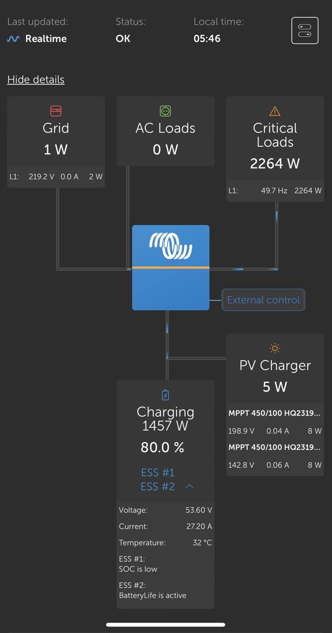
Hi all, I have a Multiplus II gx 5vka with 2x MPPT 150/60s and a FreedomWon 20/15 LifeP04 battery in an ESS configuration,

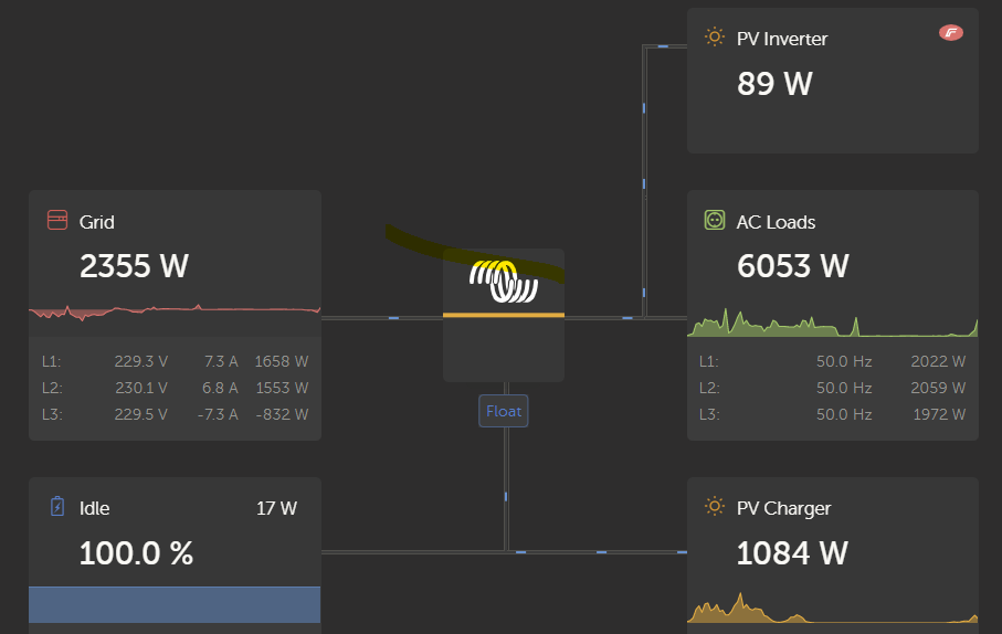
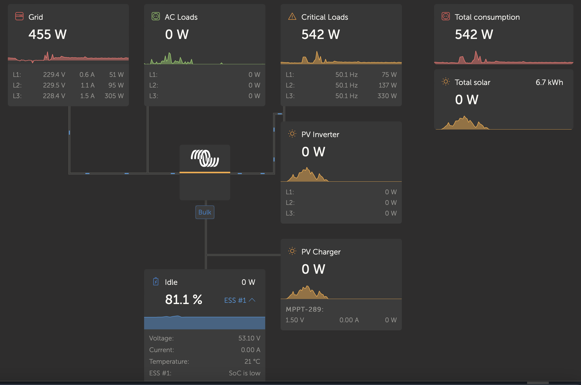
My issue is I have noticed that the grid input measurement shows that it is accurately trying to maintain my chosen grid set point of 50W however when I measure the current from the grid to the Multiplus II with an ameter i see that the power from grid to the inverter is actually around 350-400 watts. Is this a known issue with the Multiplus 2 units? is my unit just badly inaccurate?

Multiplus-IIESSVenus OS
2 comments
2 |3000

Up to 8 attachments (including images) can be used with a maximum of 190.8 MiB each and 286.6 MiB total.

Jason - UK avatar image Jason - UK commented ·
Are you using the AC in to record the grid energy use or do you have a CT sensor on the incoming supply or a connected energy meter? Asking as I did have a similar situation but it appears to have gone away before I had a change to investigate further. I am currently using the Victron 100A CT sensor to record grid energy used as I have other loads connected to AC in.
0 Likes 0 ·
mondeoman avatar image mondeoman commented ·

You can't measure power in AC circuits with the Ampmeter. The current could also be due to REACTIVE power.

With alternating current, you could have 2 Amps RMS of current in the wire and only 20W of active power.


0 Likes 0 ·
8 Answers
mahendral avatar image
mahendral answered ·

i have a similar issue - see attached. How do i fix this?

ml.jpeg


ml.jpeg (46.4 KiB)
2 |3000

Up to 8 attachments (including images) can be used with a maximum of 190.8 MiB each and 286.6 MiB total.

marekp avatar image
marekp answered ·

@RobinCG

Grid set point is the value the system is trying to maintain but is not possible to keep it exactly.

The actual value of power transfer varies sometimes widely because system has to take data from many points and based on this info decides on its settings.

To make maters worse data needed for calculation does not come at the same time and calculations also take time.

10 comments
2 |3000

Up to 8 attachments (including images) can be used with a maximum of 190.8 MiB each and 286.6 MiB total.

robincg avatar image robincg commented ·
My concern comes from my previous setup of 5kva multiplus with a Venus GX which was pretty much accurate within 10-20 watts or so on the VRM or Remote console displays.

But yeah the discrepancy on my current system raised some alarms for me. I remember a forum post where it was mentioned that the multiplus II units might have an issue with the current sense plug which caused the displayed grid wattage to be wildly inaccurate, but alas I cannot for the life of me find that post again to confirm if it is similar to what i am experiencing.

1 Like 1 ·
marekp avatar image marekp robincg commented ·

@RobinCG

Do you have a power meter at AC-in?

0 Likes 0 ·
robincg avatar image robincg marekp commented ·
So i have a fairly basic wireless AC meter but it doesnt take voltage shifts into account so is not accurate for more than a rough idea of power usage. I use a hand held AC amp meter on the AC line to the inverter input to more accurately work out wattage at a glance.


0 Likes 0 ·
marekp avatar image marekp robincg commented ·
@RobinCG

Do I understand it correctly that this wireless AC meter is not connected to your GX device.

0 Likes 0 ·
robincg avatar image robincg marekp commented ·
Correct, I am comparing against the AC in measurement provided by the multiplus and by what I can see on my hand held ac amp clamp. the cheap ac wireless ac sensor and the amp clamp measure very close but the multiplus seems to be under reporting Grid usage by around 300 watts or so. So vrm displays between 20-90 watts on average when in reality it is closer to 300-400 watts.
1 Like 1 ·
marekp avatar image marekp robincg commented ·

@RobinCG

Is your load connected only to AC-out of MP-II?

Are you sure there are no other loads between your AC meter and MP-II?

0 Likes 0 ·
robincg avatar image robincg marekp commented ·

Yes my load is connected to the AC-OUT1, and I am certain that there are no other loads in between that could be fouling up the measurements.


Side note I would like to get an ET112 Energy Meters ET112, ET340 & EM24 - Victron Energy

to eliminate the cheap wireless ac meter and integrate the whole thing with vrm but where I am based availability is special order only and I have not yet gotten around to it.

0 Likes 0 ·
marekp avatar image marekp robincg commented ·

@RobinCG

For 1 phase system ET112 is enough.

I have 3 phase system with EM24 but even that is not assuring the same power transfer numbers.

Below two numbers from the same moment.

1. EM24

2. Independent meter

difference.jpg

As you can see there is no way for those numbers to be the same. :)

When load and production is more stable the numbers get closer.

difference-3ph.jpg


0 Likes 0 ·
difference.jpg (28.3 KiB)
difference-3ph.jpg (90.7 KiB)
robincg avatar image robincg marekp commented ·

SO I finally found the document that outlines something similar to what I am suffering. I have not been able to take my system offline as of yet to test their suggested fix as there is really no downside other than downtime to try it.


https://community.victronenergy.com/storage/attachments/28254-2021-12-mpii-esii-quaii-current-sense-socket-issue.pdf


Do you think in your experience that this could be my issue?


Robin

1 Like 1 ·
marekp avatar image marekp robincg commented ·
@RobinCG

I never used internal or external current sensor, so I cannot say how big influence this have on the accuracy of the power measurements.

Their explanation sounds plausible.

I have EM24 power meter.

0 Likes 0 ·
ppr avatar image
ppr answered ·

Hi
I have a very similar setup. Just with a new EM540 and Multiplus II 5000.

This is a picture from tonight. Grid and Load should be basically the same. But this difference .... ???!!!

1662497034020.png


1662497034020.png (57.2 KiB)
1 comment
2 |3000

Up to 8 attachments (including images) can be used with a maximum of 190.8 MiB each and 286.6 MiB total.

Alexandra avatar image Alexandra ♦ commented ·

@ppr

It is possibly the sum of the phases or possibly phase compensation for the grid input, so the total of 47W is 207w (L1) - 55W - 96W

You are drawing 207W on the phases.

0 Likes 0 ·
ppr avatar image
ppr answered ·

Thank you. But this does still look strange and I think it is somehow different. I dont get it what kind a setting this is producing. The EM540 is only used for displaying.The ESS is only configured as "keep batteries charged"

1662537645991.png


1662537645991.png (41.9 KiB)
2 |3000

Up to 8 attachments (including images) can be used with a maximum of 190.8 MiB each and 286.6 MiB total.

ppr avatar image
ppr answered ·

Hi all

I can tell you, that it looks like that this "mismatch" is coming from EM540
i disconnected it from the system and since than, readings look plausible.
I dont know what kind of settings need to be adjusted on the EM540 .......


2 |3000

Up to 8 attachments (including images) can be used with a maximum of 190.8 MiB each and 286.6 MiB total.

ppr avatar image
ppr answered ·

FYI
Just to close this case here. I found out that the Smartmeter EM540 has a defect on L3. The reason is a wrong measured or calculated power factor. That drives that thing nuts.

1 comment
2 |3000

Up to 8 attachments (including images) can be used with a maximum of 190.8 MiB each and 286.6 MiB total.

mariner62 avatar image mariner62 commented ·

@ppr did you resolve the defect on L3 of your EM540?


When I was experimenting with my EM540, I initially had the phase sequence incorrectly wired and I played around with the virtual correction facility in Carlo Gavazzi's UCS software. This didn't really work for me, but I did notice strange readings from time to time, and worked out that the meter was just reporting incorrectly. I discovered that performing a factory reset would correct the problem. After I gave up trying to use CG's virtual correction tool, I did not see the problem again. Maybe a factory reset would fix your L3 issue if you still have it?

0 Likes 0 ·
ppr avatar image
ppr answered ·

Hi

In my case, the Smartmeter had an issue on L3 with the measurement about the Pf value. I got a replacement but till now I had no time to punch it in …

2 |3000

Up to 8 attachments (including images) can be used with a maximum of 190.8 MiB each and 286.6 MiB total.

wolferl avatar image
wolferl answered ·

Hi

I have a similar issue with the EM540, but when I compare the readings from EM540 with the readings on the VEbus (N/b827eb8255c0/vebus/288/Ac/ActiveIn) there seems to be an offset on all three phases.

All MPII (3pcs) report higher values on ACin than EM540. This corresponds with the fact, that the output cannot be higher than the input (see image below). If I compare the Values of "critical loads" with the values "grid" it is not plausible. If I compare "critical loads" with the input values from the MP2 (N/b827eb8255c0/vebus/288/Ac/ActiveIn) then all values are plausible.

All my loads are connected to ACout of the MPII (3 phases). There is a direct connection from the EM540 to the ACin of the 3 MPII, no consumers in between.

Is there a need to adjust the EM540 somehow?

Btw: I have as well the problem with the phases: L1-L3-L2.


bildschirmfoto-2023-01-10-um-072901.png


2 |3000

Up to 8 attachments (including images) can be used with a maximum of 190.8 MiB each and 286.6 MiB total.