question

barryward avatar image
barryward asked

Parallel Multiplus II power imbalance

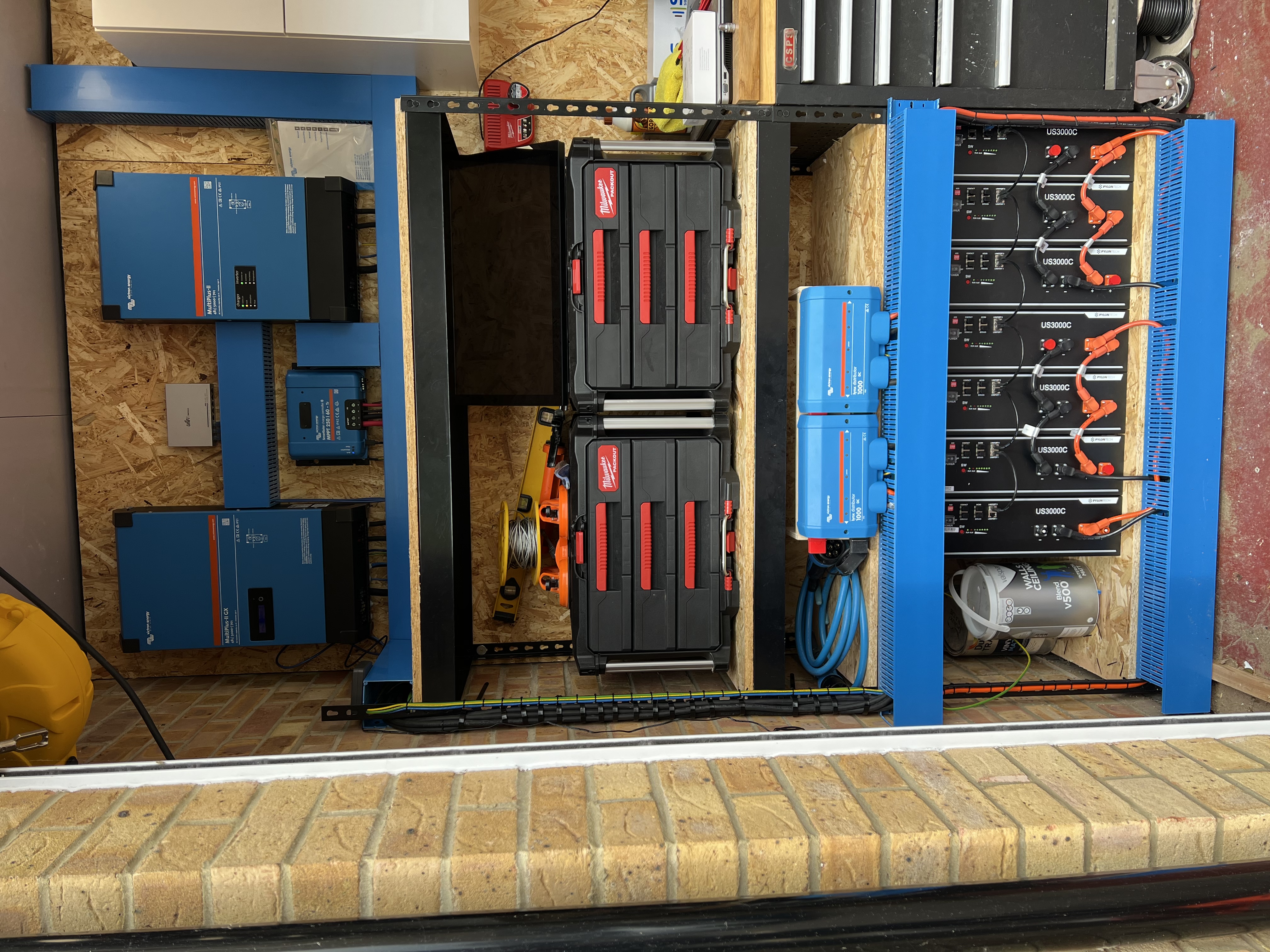
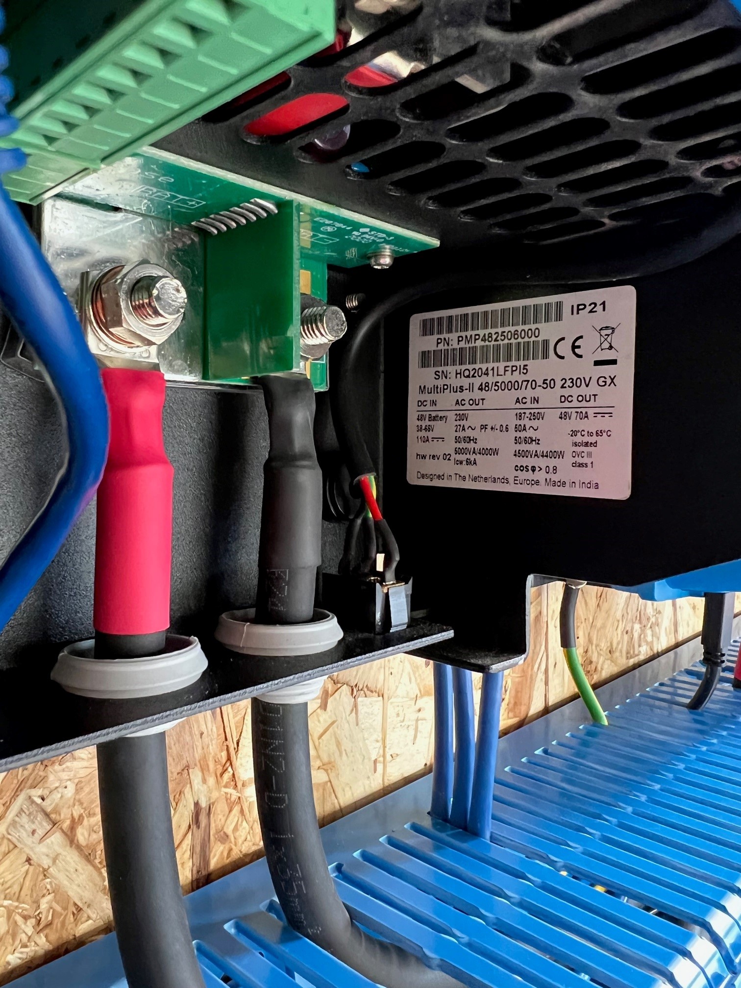
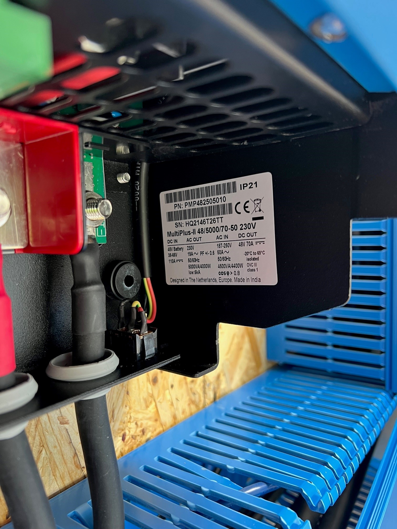
I am running 2 Multiplus II 48/5000 in parallel and am experiencing a power imbalance whilst charging and discharging, The master unit is a Multiplus II 48/5000 GX (PN: PMP482506000) and the slave is a Multiplus II 48/5000 (PN: PMP482505010) All wiring is of identical lengths of 35mm to a Victron Lynx distributer then to 7 Pylontech US3000C batteries) Charge current is limited to 60A in the master. I would expect charge current to be 120A however when charging I am seeing 60A from the Master and only 45 from the slave. During discharge the imbalance is of the same ratio. The GX has a HW label of Rev2 however the standard multi doesn't have the same info. I have attached some photos and my configuration. I have read through the parallel system documentation and also completed the training, any advice would be gratefullyLynx.jpgMaster.jpgSlave.jpg0281bef3c77a_inst_ttyS3_Interfaces_Mk2_Tunnel (3).zip received.


Barry

Multiplus-IIESSmultiplus in parallel
2 |3000

Up to 8 attachments (including images) can be used with a maximum of 190.8 MiB each and 286.6 MiB total.

5 Answers
Daniël Boekel (Victron Energy Staff) avatar image
Daniël Boekel (Victron Energy Staff) answered ·
Hi @BarryWard normal support is trough your supplier, if needed they can contact the Victron UK sales agent.


Install looks neat, can you show the AC wiring? how long / what gage are these?

It could indeed be that hw revision is of influence, but most systems work fine when wiring is ok.


6 comments
2 |3000

Up to 8 attachments (including images) can be used with a maximum of 190.8 MiB each and 286.6 MiB total.

barryward avatar image barryward commented ·

Thanks Daniel, I’ll try with the dealer first but when I spoke to them previously they were reluctant to include Victron support as the units were compatible.

Cabling from installation to consumer unit is 2 10m runs of 6mm 5core H07F each carrying AC in and Out from the inverters, both cables following same route too, I have attached pictures, the CU wiring has been pulled out to accommodate the current clamps whilst fault finding

af43efd0-8f73-438f-bcaf-55b544438288.jpeg


e6488a9f-bb0c-4521-84b3-08e658df23c9.jpeg

Would AC cabling have an impact on charging balance? I can understand DC having an impact but not sure how AC would cause such an imbalance.

After talking to @MarekP it seems our versions are almost the same from build dates and have very similar issues although very different system configuration. At this stage I’d be happy to swap out the GX for an identical MP2 and add a Cerbo to keep everything identical main reason for going parallel was for charging current. I need to be able to charge 9 pylontech us3000c in a small offpeak window.

0 Likes 0 ·
Kevin Windrem avatar image Kevin Windrem barryward commented ·
All inverters running a parallel have the same duty cycle. The current in each unit is a function of wire and internal circuit resistances in both the AC and DC paths. So if there is a difference in the AC wiring resistances, the currents won't be the same.


This is explained better in the training.


So all paths must be the same length and gauge: AC input, AC output, DC. This is from each inverter to a common point somewhere in each path. Your Lynx Distributor for the DC path. My guess is the box with breakers you show will be your AC input and output common points.

0 Likes 0 ·
marekp avatar image marekp Kevin Windrem commented ·
@Kevin Windrem

If you look closely at the ratio between internal resistance and AC wires resistance, you will see that the external AC wires would have to be hundreds of meters long to make internal resistance irrelevant.

I suspect that diference in internal resistance of the two inverters in @barryward setup is substantial and cannot be compensated with resistance of external AC wires.

0 Likes 0 ·
Daniël Boekel (Victron Energy Staff) avatar image Daniël Boekel (Victron Energy Staff) ♦♦ barryward commented ·
Hi @BarryWard 10m cable 6mm2 each is pretty good and rules out the AC cabling as a factor.


You do know the current clamps don't function on a parallel install correct? as they are supposed to measure grid power. and the system would be confused due to the measured value being doubled internally in a parallel system.

0 Likes 0 ·
barryward avatar image barryward Daniël Boekel (Victron Energy Staff) ♦♦ commented ·
@Daniël Boekel (Victron Energy Staff), for the installation I’m using an ET112 on the main incoming grid supply, the current clamps are part of my data logger
0 Likes 0 ·
Daniël Boekel (Victron Energy Staff) avatar image Daniël Boekel (Victron Energy Staff) ♦♦ barryward commented ·
I've sent you an email.
0 Likes 0 ·
marekp avatar image
marekp answered ·

@BarryWard

You have over one year difference in production dates.

I had similar problem with my MP-II/3k parallel setup.

https://community.victronenergy.com/questions/91403/how-to-balance-2-mp-iis-in-parallel.html

3 comments
2 |3000

Up to 8 attachments (including images) can be used with a maximum of 190.8 MiB each and 286.6 MiB total.

barryward avatar image barryward commented ·

I read your post and thought it sounded very similar however my distributer is adamant they are compatible and cant provide any help. The serial numbers of the two units are...

Master: HQ2041LFPI5
Slave: HQ2146T26TT

0 Likes 0 ·
marekp avatar image marekp barryward commented ·

@BarryWard

My distributor, before ordering, asked Victron if the new unit is ok for parallel use with my old and was told that it is ok.

In reality it was not.

When I see design difference in your units (battery terminals) is like seeing mine.

Your units are 57 weeks apart in production dates.

Mine were 68 weeks.

0 Likes 0 ·
barryward avatar image barryward marekp commented ·
Thanks for the information, I will speak again with the supplier and see if i can get them to raise a ticket with Victron. Much like yourself, everything I have checked and double checked, all resistances are equal, connections torqued correctly, this is the only thing left.
0 Likes 0 ·
barryward avatar image
barryward answered ·

Just as an update to the power imbalance, I am also experiencing overvoltage in charging and the system is unable to maintain a steady grid setpoint. I am now seeing wild swings between 500w import to export continuously. I’m going to reconfigure the system back to a single Multiplus for now. what is the best way forward with this, could you put me in touch with someone in UK support so that we can work this out with the distributor please.

1 comment
2 |3000

Up to 8 attachments (including images) can be used with a maximum of 190.8 MiB each and 286.6 MiB total.

vward avatar image vward commented ·

How much of an imbalance is there? I've found that two Multipluses in parallel (offgrid) struggle to charge equally using a generator.


Differences were worse when I found that VE configure tends to not update very well, I had to double and triple check values for charge current were saved and uploaded. Often one multi wouldn't update and the other would, so ensuring all parameters in both multis were the same was very tricky.

Tested with a clamp meter at the multis and at the generator. And then double checked this result with our installer, who brought HIS clamp meter over too. The multis are RIGHT next to each other and no difference in cable length.

The slave multi was consistently lower current than the master. But not by a lot. about .5 amps.


PS. our date of manufacture is pretty much the same

0 Likes 0 ·
Craig Robinson avatar image
Craig Robinson answered ·

Just a general question the AC output live from each multi 2 do they both go through their own MCB and the output from the MCB linked together to feed the distribution board or do you not bother adjust join the AC outputs together then feed the distribution board, been struggling to fine any clear diagrams on this

4 comments
2 |3000

Up to 8 attachments (including images) can be used with a maximum of 190.8 MiB each and 286.6 MiB total.

nickdb avatar image nickdb ♦♦ commented ·
Each input and output should be independently protected with their own breakers, so they can be individually isolated, then main breakers for overall supply and output.
0 Likes 0 ·
ponzoa avatar image ponzoa commented ·
I bring them both into the same breaker and RCB as they are really one unit when in parralel. If you switch one off, you switch them all off.
0 Likes 0 ·
nickdb avatar image nickdb ♦♦ ponzoa commented ·
Local regs may not appreciate that approach.

If one inverter acts up and you want to revert to standalone, to test or to keep running, then that becomes more limiting.

0 Likes 0 ·
ponzoa avatar image ponzoa nickdb ♦♦ commented ·
You can test and diagnose in standalone with the breaker off. What's more, this would be the recommended approach so you don't conenct to the internal distribution nor the grid until your satisfied everything is up and running correctly.
0 Likes 0 ·
janvi avatar image
janvi answered ·

Double check all connectors screw torque (AC+DC) I had 2kW phase diffrences for a 6 pcs MP2-5000 setup. Once the LV connectors are hot, they become corrossive. Similar problem if your cable lugs are not crimped well. If you have fuses on your busbar, check nominal size and voltage drop over fuse what might be pre-damaged for any former reasons but not melt down completely. Meassure the input voltage at your MP2 under load as accurate as possible and compare. A thermal image also helps from where the problems come.


2 |3000

Up to 8 attachments (including images) can be used with a maximum of 190.8 MiB each and 286.6 MiB total.