question

pvcampbell avatar image
pvcampbell asked

How to use Cerbo GX Relay 1 with timing relays to autostart Onan Generator with 3-wire setup

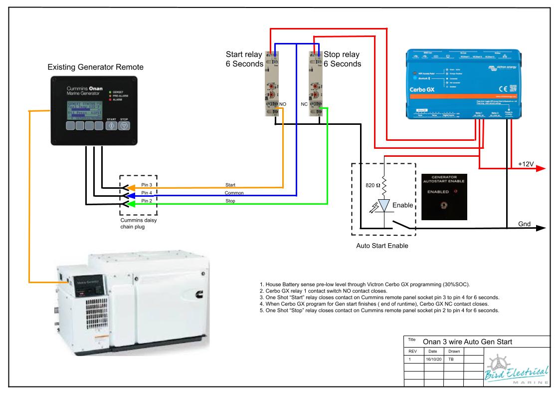
I am attempting to use the auto generator start routines on the Cerbo GX using relay 1 to start my Onan generator, which has a 3-wire setup with momentary switching for both start and stop. I have two Crouzet MUR3 relays, as recommended by Victron at this link:

https://www.victronenergy.com/upload/documents/Automatic_Generator_start-stop/Automatic_Generator_start_stop-en.pdf

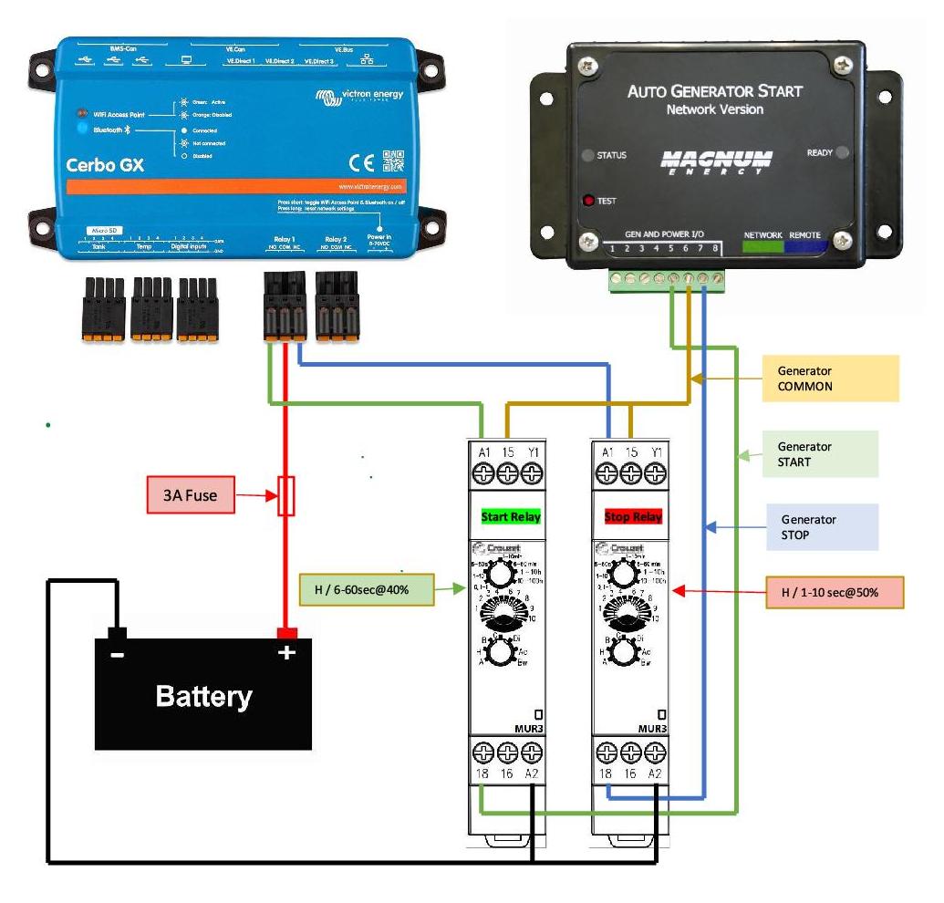
The wiring diagram provided by Victron in this link is very confusing to me. I have wired the relays as I think it shows, but I get nothing to work. I can hear the Cerbo relay kick in, the nothing happens with the MUR3. As I interpret the diagram, there is no power fed to the MUR3, so I don't know how it actuates the internatl relay.

Can anyone give me a better explanation of how this wiring diagram works? It appears that the A2 terminals on the relays go to battery negative - is that correct? Don't the MUR3 relays need power to actuate their relays? If so, where is that power shown in the wiring diagram?

Any help with this would be appreciated.


cerbo gx
2 |3000

Up to 8 attachments (including images) can be used with a maximum of 190.8 MiB each and 286.6 MiB total.

5 Answers
sec0pz avatar image
sec0pz answered ·

I used the above diagram from pvcampbell, but different relays ( 2x GEYA GRT8-M1). Basically, I added a ground and power to the input side of the relay. Using only 2x relays, one start and one stop, I can start and stop my Onan Cummins 7000 QC generator. Additionally, I changed the relay base function from "H" type (ON/OFF DELAY)??? to "F" type (ONE SHOT DELAY).

Now that I figured out how the relays work, I am thinking about adding a third relay, just for "Priming". More to come on that. Still a work in progress, but I can remote start and stop the generator from the internet which means my route will stay online, which means my tunnels will stay up and I can control my thermostat from anywhere.

If there is interest, I am happy to create a drawing. Thank you all for blazing a trail ahead of me making it easier for me to integrate. "I stand on the shoulders of GIANTS!"

V/r,

sec0pz

4 comments
2 |3000

Up to 8 attachments (including images) can be used with a maximum of 190.8 MiB each and 286.6 MiB total.

johnathanhall avatar image johnathanhall commented ·
I would love a diagram even if crude. I am getting ready to hookup a 12k Onan. just the want the CERBO to control when it starts/stops based on SOC and then to be able to do it remotely as well.
0 Likes 0 ·
econger avatar image econger johnathanhall commented ·
Did you ever get a diagram?
0 Likes 0 ·
tomacable avatar image tomacable commented ·
Could you send me a wiring diagram please
0 Likes 0 ·
tomacable avatar image tomacable commented ·
You can send it to tomacable@gmail.com

Thanks

0 Likes 0 ·
jamierobinson avatar image
jamierobinson answered ·

Hi PVCampbell.

It looks to me like you put Gen start battery + to the Com terminal on the Cerbo then NO is your start signal and the NC is the stop signal. The relays have a permanent neg. connection to A2 and your start/stop signal goes to A1. This will activate the timers on the relay and the start and stop signal pulses come from terminals 18 from the relays.

Hope this helps

2 |3000

Up to 8 attachments (including images) can be used with a maximum of 190.8 MiB each and 286.6 MiB total.

pvcampbell avatar image
pvcampbell answered ·

I finally got this figured out. Attached is a diagram of the wiring that works. I am using this in conjunction with a Magnum AGS unit, so I've wired onto the terminal blocks for the Magnum unit, but the generator start, stop and common connections could be wired directly to the generator if the Magnum AGS didn't exist.

ags-wiring-diagram1.jpg


2 |3000

Up to 8 attachments (including images) can be used with a maximum of 190.8 MiB each and 286.6 MiB total.

Trevor Bird avatar image
Trevor Bird answered ·

This is how we do it,

onan-3-wire-cerbo-configuration.jpg


1 comment
2 |3000

Up to 8 attachments (including images) can be used with a maximum of 190.8 MiB each and 286.6 MiB total.

rmshapiro avatar image rmshapiro commented ·
Found this old answer - exactly what I want to implement. Question: what wire harness is used to connect the generator remote to the relays?
0 Likes 0 ·
803m avatar image
803m answered ·

Based on the diagram without the Magnum AGS is the following understanding correct? The Cerbo creates a generator auto start command based on a parameter like low voltage. If the generator fails to start the low voltage will cause the Cerbo to initiate another auto start command until the low voltage state is addressed by a running generator producing power. If so would the same apply if the start command was initiated by me remote starting vs low voltage auto start from the Victron app?

2 |3000

Up to 8 attachments (including images) can be used with a maximum of 190.8 MiB each and 286.6 MiB total.