I have a bilge alarm system that outputs 12v when triggered. I have wired it to a digital input on the Cerbo through a DC/DC converter that outputs 3.3v. But I'm not getting expected results. On the Cerbo unit, the alarm state only changes when power is removed from the input. Conversely, when 3.3v is applied to the digital input (the system is triggered), the alarm state does not change. The ultimate goal is to have the unit register an alarm state when the bilge alarm system is triggered. Does anyone have any insight for me? Thanks.
asked
Cerbo GX Digital Input Connection to Bilge Alarm
Hi @Zach McAbee I have a similar bilge alarm setup using a 12V relay to trigger the digital input. I suspect you need to enable the 'Inverted' and 'invert alarm logic' settings. 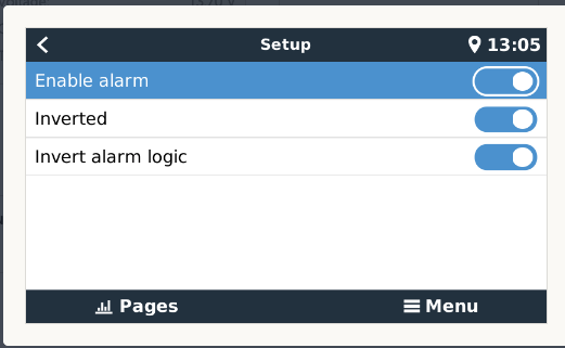
Hi @Sarah . Many thanks for your answer. Yeah, I've played with those settings quite a lot. My issue persists no matter what I choose for these settings.
I'm not sure if it's good idea to apply an external voltage to the digital input.
For testing try to just connect a wire loop to one of the inputs. If that works you have to connect the coil of a relay to your 12V signal and the contacts of the relay to an input of the Cerbo.
Hi @Matthias Lange - DE . Thank you for responding. The bilge system that I want to trigger the alarm outputs 12v and does not contain any non-voltage switches. So are you saying that I cannot connect the cerbo to such a system? If you're not saying that, do you have an opinion on how I should accomplish it? Many thanks...
Sorry @Matthias Lange - DE . I should have contemplated your answer more before responding. I think I get what you're saying: I should connect the 12v output from the bilge system to a relay, which will open/close a non-voltage circuit. Correct?
I searched out this thread having just added a bilge alarm with a NO relay contact across a digital input. There is no inverting applied and it repeatedly goes into alarm a short time after clearing. The input circuit is 18AWG running about 20' total loop length to the relay contacts. Could voltage drop be causing an ambiguous state on the input? If so, what is the max advised length? I should add that when I view the device list the input status is 'OK' even when its showing an active alarm. I am observing this remotely.
I am trying the same thing on my Cerbo GX. I have added a relay. An opto coupler will work as well. When connected into the bilge pump + wiring, the presence of a + charge will trigger the relay/optocoupler to trigger the digital input. minimal voltage is passed on to the Cerbo GX.
I am using the following relay from Amazon. Working so far in my testing.
https://www.amazon.com/gp/product/B00M1MZN4I/ref=ppx_yo_dt_b_asin_title_o00_s00?ie=UTF8&psc=1 This relay can mount on a DIN bar, and have positioned it next to the Cerbo GX on the DIN Bar.
https://www.amazon.com/gp/product/B08LT22787/ref=ppx_yo_dt_b_search_asin_title?ie=UTF8&psc=1
https://www.amazon.com/gp/product/B01FT485S0/ref=ppx_yo_dt_b_search_asin_title?ie=UTF8&psc=1
Thank you @Matthias Lange - DE . I wired in a relay as per your suggestion and everything works now.
I am considering adding a motion sensor to the Cerbo
this is the device
2PCS PIR Infrared Motion Sensor, Adjustable DC 12V~24V PIR Human Body Motion Sensor Detector Switch for LED Strips Lighting Lamp Automatic (Black & White)
the device outputs whatever voltage is input to run the device. Do I need a dc to dc converter to reduce voltage to 3.3 volts so I don't damage the cerbo?
Just use the sensor voltage to trigger a relay. Connect the NO and COM of the relay to the digital input 3.3 and ground.
does negative/ground go back to the device or to ground for the battery?
Thank you in advance
Sorry I should have been more clear. Connect the NO and COM of the relay to the digital input DATA and GROUND of the cerbo.
Hi,
I added optocopplers exactly for this. The bilge pump drives the 12V LED input of the optocoppler and the open collector is connected to the digital input. Result: less consumption, galvanic separation and open collector to avoid any possibility to destroy the digital input. The only thing is that the invert function has to be activated...