question

mresman avatar image
mresman asked

Alignment of BMV and Smart Solar voltage values

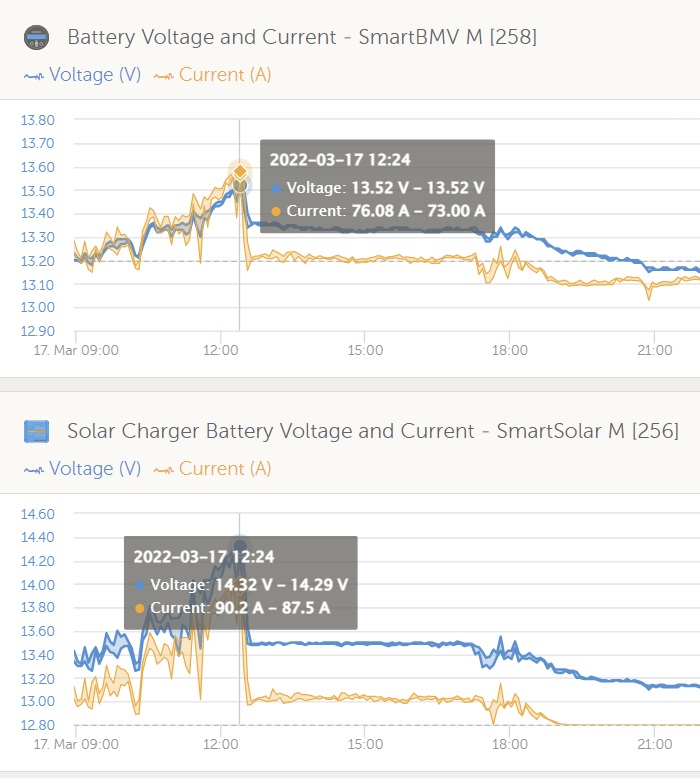
I have a BMV-712 and SmartSolar MPPT 150/100 managing my Relion RB300 Lithium batteries. I have VE.smart networking to report the battery voltage and current to the MPPT. The MPPT reports a battery voltage of 14.0 volts while the BMV shows 13.5V. Should they not be the same if VE.Smart is reporting the battery voltage? There is a drop in voltage due to the cable length between the MPPT and where they connect to the battery bank, but the VE.Smart should take care of this.

Any ideas?

MPPT ControllersBMV Battery MonitorVE.Smart Network
2 |3000

Up to 8 attachments (including images) can be used with a maximum of 190.8 MiB each and 286.6 MiB total.

6 Answers
mresman avatar image
mresman answered ·

I found this paragraph in the MPPT's User Manual.

Section 5.5 VE.Smart Network
The VE.Smart network can be used for:

• Temperature sensing - the measured battery temperature is used by the chargers in the network for temperature compensated charging and in case of lithium battery for the low temperature cut off.

• Battery voltage sensing - the measured battery voltage is used by the chargers in the network to to compensate the charge voltage should there be a voltage drop over the battery cables.

• Current sensing - The measured battery current is used by the charger so it knows the exact tail current at which the absorption stage should end and the float (or equalisation) stage should start.

To measure the charge current all charge currents from all chargers are combined, or if a battery monitor is part of the network the actual battery current will be used.


1 comment
2 |3000

Up to 8 attachments (including images) can be used with a maximum of 190.8 MiB each and 286.6 MiB total.

Alexandra avatar image Alexandra ♦ commented ·

https://www.victronenergy.com/media/pg/VE.Smart_Networking/en/voltage,-temperature-and-current-sense---further-details.html


2. Voltage, temperature and current sense - further details

The battery voltage data is used to compensate for voltage-drop over the battery cables. This ensures that the battery is charged with the exact voltage as configured in the charger - instead of a lower voltage due to resistance in the wiring.

0 Likes 0 ·
Alexandra avatar image
Alexandra answered ·

@mresman

The mppt will report/record what it is reading.

The bmv will report/record what it is reading.

The real question really then, is the battery being charged to the the correct charged voltage set for the batteries?

Voltage drop over a cable would mean the battery would be undercharged normally. In this case it seems as though the mppt is compensating for the voltage drop over its cable using the bmv reading, at least I assume that is what is happened there since I cannot see the system.

4 comments
2 |3000

Up to 8 attachments (including images) can be used with a maximum of 190.8 MiB each and 286.6 MiB total.

mresman avatar image mresman commented ·
I suspect that means that the Battery Voltage by the MPPT is the voltage at the MPPT's battery terminals. OK - does the MPPT use the BMV's reported voltage value, via VE.Smart, to decide that it will flip into Absorption Mode? So, if the Absorption voltage is set to 14.2V, then the MPPT's Battery Voltage will be greater than 14.2 when it goes into Absorption Mode.
0 Likes 0 ·
Alexandra avatar image Alexandra ♦ mresman commented ·

@mresman

That would be the thing to double check. use a meter at the battery if you like and make sure it is reaching the absorption voltage.

I would expect or consider it normal of the mppt voltage to read higher than it was set if it is using the bmv reading for charging. The amount difference will also vary depending on how much current is passing over the cable as well.

Bulk and absorption are the same set target voltage, so the difference between the two stages of charging is actually current draw. It can remain in bulk for a bit of time at 14.2 before switching charge stage.

0 Likes 0 ·
garry-crothers avatar image garry-crothers commented ·
I have the same issue with my Bmv712. But slightly complicated by the fact I'm using two different smartsolars New 100/50 and older 100/30. All with 3.11 firmware. But I only see the difference in displayed voltage on the newer 100/50.

Bmv & 100/30 & separate multimeter all confirm identical voltage. But 100/50 reads 0.2v lower.

All networked correctly and communicating fine. I've defaulted and reprogrammed to no avail.

I'll clean all connections next. But it does look like the mppt's are reporting the voltage on their battery inputs. And I would have expected the charge modes to be driven by the BMV to get rid of any cable loss errors


0 Likes 0 ·
Alexandra avatar image Alexandra ♦ garry-crothers commented ·

@Garry Crothers

0.2v is within measurement tolerances. It is not unusual to see even a 0.2v difference using two different good digital multimeters (like the ones with 3% counts/tolerance there is a more technical term I am sure) on the same point in wiring.

Some cheaper meters up to 10%, so beware of a cheap meter. In all honesty 0.2V variation is not bad at all.

You will notice most manufacturers have a variation of abiut 0.3 or 0.4 v for charge and float voltages to accommodate for this variable.

0 Likes 0 ·
mresman avatar image
mresman answered ·

Do you know if there is any Victron documentation indicating that the MPPT uses the VE.Smart's Battery Voltage to make its decisions?

2 |3000

Up to 8 attachments (including images) can be used with a maximum of 190.8 MiB each and 286.6 MiB total.

mresman avatar image
mresman answered ·

Here is my current example of this issue. For the last couple of days my MPPT has been going into FLOAT, and my battery charge is at 80% ish. Attached is an image of that occurrence yesterday. The MPPT thinks the battery voltage is at 14.2 and move to FLOAT as expected, yet the BVM shows the battery voltage at 13.5V. This is while the MPPT and BVM are communicating voltage and current vis VEDirect. So the MPPT is using its Battery voltage at its battery connection to switch the charging state.


After the shift to Float, the battery voltage at the battery terminals are 0.17 volts different due to voltage drop over the battery cables leading out of the MPPT - as expected.

Why isn't the VEDirect voltage the driving factor in the MPPT's charging state?

incorrect-mppt-battery-voltage.jpg


1 comment
2 |3000

Up to 8 attachments (including images) can be used with a maximum of 190.8 MiB each and 286.6 MiB total.

klim8skeptic avatar image klim8skeptic ♦ commented ·
Have you Smart networked the mppt & BMV?

Or are you using DVCC?

0 Likes 0 ·
mresman avatar image
mresman answered ·

Some additional data - I may be having an issue with the VESmart from the BMV reaching the VESmart of the MPPT. They see each other at times, but not always.

As I have both devices connected to a CCGX via VEDirect, can that be used to communicate the battery voltage, not the wireless connection?

I tried to understand the DVCC control, but that seems to be targeted to smart batteries, which mine are not. Is this a doable approach and I am just not figuring it out?

2 |3000

Up to 8 attachments (including images) can be used with a maximum of 190.8 MiB each and 286.6 MiB total.

ako avatar image
ako answered ·

Thought i would add what i have observed thinking it might clarify the issue . The MPPT will show the voltage its sending out at its Battery terminals as it has to supply a higher voltage in order for it to charge the batteries so the Battery terminals will show a lower Voltage depending on the cable loss . I took readings and closely watched and believe i have now sussed it out . I will explain my findings in the hope it wil make sense . Measuring with an accurate Multimeter early morning when charging has only just begun i see a voltage of 24.75 Volts on my Battery Terminals but the VRM and Victron Connect App both show 24.95 Volts , the actual reading at the MPPT battery Terminals also shows 24.95 volts , a difference between it and the battery terminals of 0.20 Volts , as the morning progresses and the Batteries charge the difference gradually decreases until its almost gone by the time the MPPT enters Absorption so there's no reason for it to be showing a greater voltage as by then the loss in the cables is accounted for and overcome .

I have only a few days ago installed a 150/70 MPPT and this voltage difference between Battery Terminals , MPPT terminals supported by VRM and Victron Connect App has been bugging me but now after a couple of days monitoring them and practically being able to predict what one voltage will be from knowing the other and the duration that they have been charging .

The most important aspect for me is to be able to look online at the voltage of my batteries at night and know its correct which it is because at night the MPPT is only reading the Voltage and not providing a charge to distort it .

I use DVCC on the Cerbo to communicate Voltage and Temperature and they work fine . The Cerbo is taking the Temperature from a Temperature Sensor that is identical to the one supplied with the Multiplus and the Voltage from the Bus Bar , the MPPT is also connected to it so they are both receiving the same voltage as the Battery Terminals but the MPPT provided additional voltage at its Battery Terminals in order to charge .

2 |3000

Up to 8 attachments (including images) can be used with a maximum of 190.8 MiB each and 286.6 MiB total.