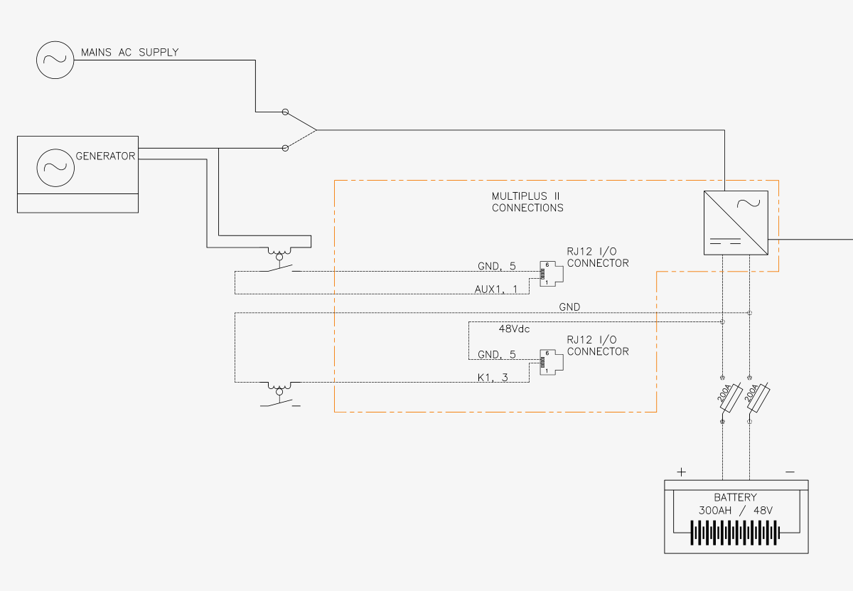
On the MultiplusII RJ12 I/O, I wish to use the Aux1 input to detect a switch event, (Generator transfer switch is on), AND use the K1 relay (open collector), with 48Vdc from the battery, to run a separate relay. I presume those two can't be used together, where I put 48V to the Ground pin of the RJ12 IO connector for the K1 relay, but which would also maintain the Aux1 in the "high" state. And if the Aux1 is pulled high, rather than to ground, it will not work if I attempt to ground it with my switch event. Is that right? Do I need to leave Ground without any voltage, to use the Aux1 pin as in input? That is, not use both a relay to K1 and an Aux input at the same time?
asked
Multiplus II - using Aux1 input and K1 Relay at the same time: possible?
Please make a diagram of what you want to connect, I'm not sure what you want to do, but in any case don't put an external voltage on the inputs.

The aim was to have a manual transfer switch for a generator, trigger the first relay (AC-coil on relay), to tell the MPII that the generator is on (not the grid), and to reduce AC-current in down to 8Amps. the second relay shunts the PV (micro inverters) out of the AC-Out (they are AC coupled), when Battery SOC reaches a certain (high) level. Typically this setup is done using a quattro (ie - with an AC1-in & AC2-in), however, this also needs to be grid connected in Australia...where the Quattro doesn't have local approval for grid connected with feedback/anti-islanding.
The alternative is to move one relay to the VenusGX (ie the battery SOC relay), which will solve the problem (I wanted to use the MPII main relay for loss of mains trigger, along with the battery SOC, in "AND" logic configuration.) Easy enough to move that second relay on K1 to the VenusGX...just started with a remote ColorGX, which required slightly more cabling to get to that relay...
Have a look at assistants and how they work, but yes you can use both at the same time for different tasks
https://www.victronenergy.com/live/assistants:start
https://www.victronenergy.com/live/assistants:how_to_add_and_configure_an_assistant
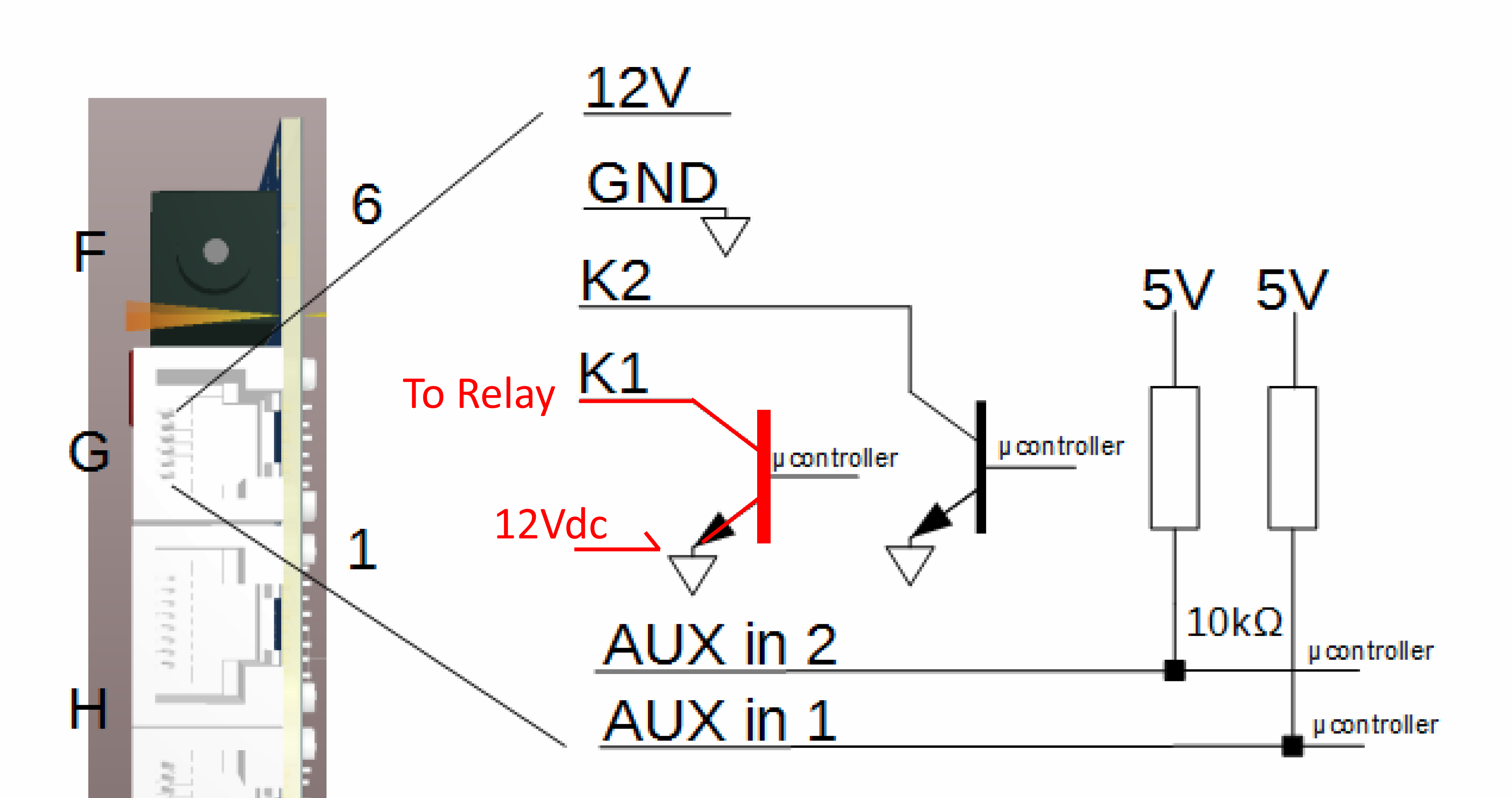
The main question I had, was is that (image above) how the dry contact usually works for the K1-Gnd, when used as a relay? That is, would it be usual to put say 12Vdc to the Gnd pin, then when the contact (K1 in this case) driven by the assistant closes, that can run another main relay, with a 12Vdc coil? If not, how would a relay work, via an assistant, from the K1/K2 pins? Thanks,
what you are describing is a digital output, not to use for driving relays etc. I think, but for communication with other devices.
The manual is not very clear on the relay, as it is called 'alarm contact' there...
https://www.victronenergy.com/upload/documents/Manual-MultiPlus-II-48V-3k-and-5k-230V-EN-NL-FR-DE-ES-SE.pdf
What I assumed is the programmable relay, is called the 'alarm relay' in the manual, in the quick installation guide it is called the 'aux relay', when you use this you have a real relay,
https://www.victronenergy.com/upload/documents/Quick-Install-Guide-MultiPlus-II-48V-3000VA-230Vac-EN.pdf
and if you drive a relay coil, please use a suppressor diode (wrong word for that?) in parallel with the coil otherwise you'll damage the switch that drives it (in this case: the relay contact in the Multi)
OK, that sounds about right, although I did see in another post that someone had done exactly what I proposed: "bridge 24V to GND, to operate K1 as a relay", although perhaps I mistook that... I will avoid using that digital out as a relay, and instead use my first option, which is the main Multiplus relay + the VenusGX relay, in series. That will work. As to the diode, is that needed for the main MP or VGX relays? I have not seen mention of the diode for relay use before...
Always use a diode if you're driving a relay with DC. look it up if you don't know why.
Why not use the auxilary relay of the Multi? I don't get it, you want one input and one output right? (at least in your drawing)
The Multiplus-II has only 1 relay, I believe you refer to the Multiplus (standard) versions, which appear to have 2 relays. So, for additional relays...as far as I can tell, it is necessary to use those dry contacts (ie as a digital output), although I can't see how it would be possible without putting a voltage through ground, to drive a relay coil without more electronics (putting 12v to ground was what another person did, see here: https://community.victronenergy.com/questions/5747/onan-auto-gen-start-with-ccgx.html. Doesn't seem right to do that, so...I will use the Venus GX relay.
I think the "alarm contact" is the main relay on the MultiplusII, from what I can tell...(not the extra digital outs...K1, K2). IE an isolated relay, suitable for operating a secondary relay, or for doing switching of a voltage itself.